- País
- Estados Unidos
- Fabricante / Marca
- Admiral (brand) Continental Radio & Television Co.; Chicago, IL
- Año
- 1951 ?
- Categoría
- Radio - o Sintonizador pasado WW2
- Radiomuseum.org ID
- 31258
-
- alternative name: Continental Radio & TV


Q = ebay objnr : 280071833704

Q = ebay objnr : 280071833704
Q = ebay objnr : 280071833704
Q = ebay objnr : 280071833704
Q = ebay objnr : 280071833704

Q = ebay objnr : 280071833704

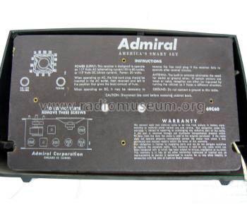
RECONSTRUCTED LABEL
Haga clic en la miniatura esquemática para solicitarlo como documento gratuito.
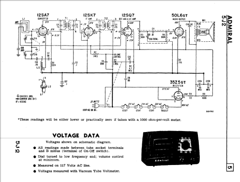
- Numero de valvulas
- 5
- Principio principal
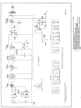
- Superheterodino en general; ZF/IF 455 kHz; 2 Etapas de AF
- Número de circuitos sintonía
- 6 Circuíto(s) AM
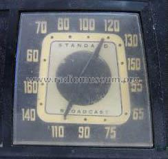
- Gama de ondas
- OM (onda media) solamente
- Tensión de funcionamiento
- Red: Aparato AC/DC. / 117V = 110 -120 Volt
- Altavoz
- Altavoz dinámico (de imán permanente) / Ø 5 inch = 12.7 cm
- Material
- Plástico moderno (Nunca bakelita o catalina)
- de Radiomuseum.org
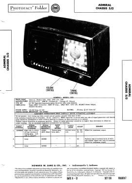
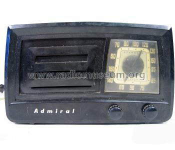
- Modelo: 5J21 Ch= 5J2 - Admiral brand Continental
- Forma
- Sobremesa de cualquier forma, detalles no conocidos.
- Anotaciones
-
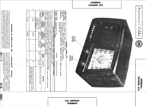
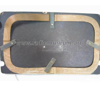
Admiral model 5J21 is an AC-DC operated superheterodyne receiver with loop antenna.
Color= Ebony, chassis 5J2 is identical to 5E2.
- Ext. procedencia de los datos
- Ernst Erb
- Procedencia de los datos
- Collector's Guide to Antique Radios 4. Edition
- Referencia esquema
- Beitman Radio Diagrams Vol. 11, 1951
- Documentación / Esquemas (1)
- Rider's Perpetual, Volume 22 = covering 1951
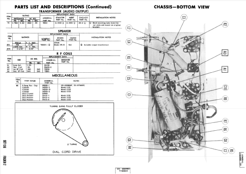
- Documentación / Esquemas (2)
- Photofact Folder, Howard W. SAMS (Date 6-1951, Set 136, Folder 2)
- Documentación / Esquemas (3)
- Photofact Folder, Howard W. SAMS (Set 136, folder 2, dated 6-51)
- Otros modelos
-
Donde encontrará 3227 modelos, 1332 con imágenes y 2592 con esquemas.
Ir al listado general de Admiral (brand) Continental Radio & Television Co.; Chicago, IL
Colecciones
El modelo 5J21 es parte de las colecciones de los siguientes miembros.
Contribuciones en el Foro acerca de este modelo: Admiral brand: 5J21 Ch= 5J2
Hilos: 2 | Mensajes: 2
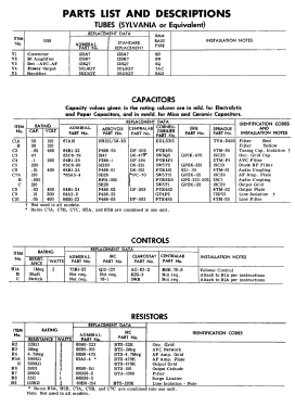
The Sams photofact with 136-2 on it at first glance on the screen looks like the 50L6 has a #1 pin connection however when enlarged/ printed it is an 8. The other schematics on the various iistings here have a #1 when enlarged or printed out. Also this schematic has the correct and easier to understand boxed in area for C7/R5 which is a combined Capacitor and resistor that looks like a 2x3 cm square flat capacitor. The boxed in area with it's individual parts diagrammed out allowed me to easily replace the combined part with 5 different resistors and capacitors .
Michael Saija, 15.Jun.19
The 50L6 tube has NO number 1 pin. The schematics show a 150 ohm resistor from pin 1 to chassis ground however in reality ( and it shows on the Sams photo's) the number 1 position on the socket is grounded to chassis. The 150 ohm resistor actually goes from the #8 pin to the #1 pin socket position and thence to chassis ground.
Michael Saija, 15.Jun.19