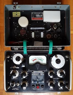
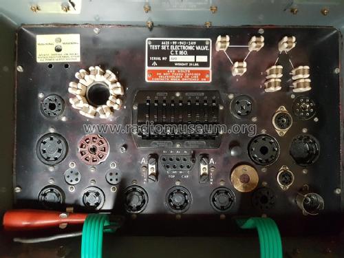
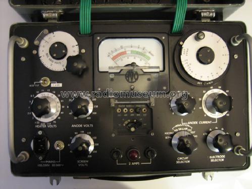
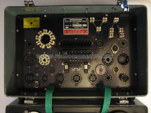
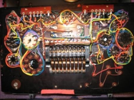
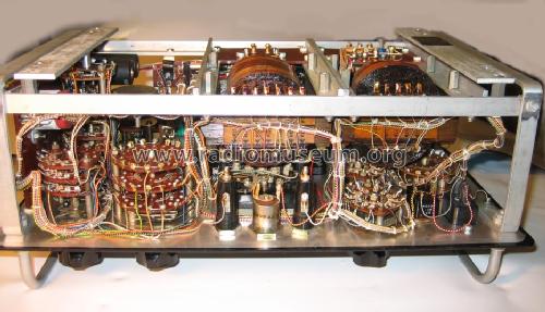
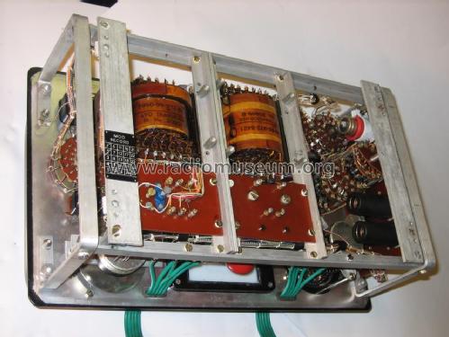
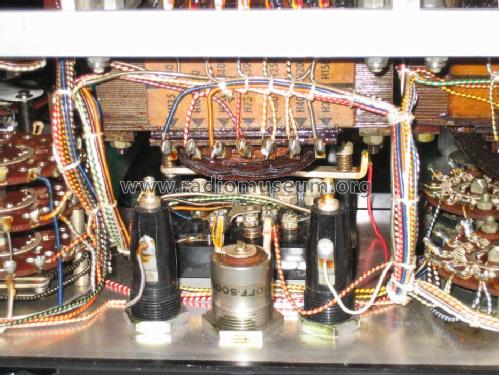
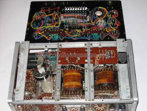
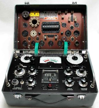
Test Set Electronic Valve C.T.160
Avo (Brand), Automatic Coil Winder and Electrical Equipment Co., Avo Ltd; London
- Pays
- Royaume Uni
- Année
- 1960
- Catégorie
- Appareils de mesure et de dépannage (matériel de labo)
- Radiomuseum.org ID
- 113160
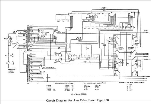
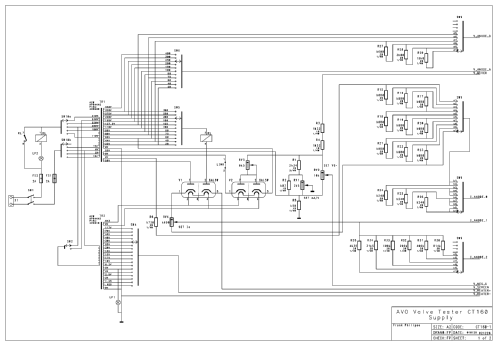
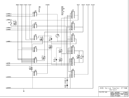
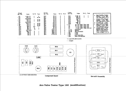
Cliquez sur la vignette du schéma pour le demander en tant que document gratuit.
- No. de tubes
- 2
- Gammes d'ondes
- - sans
- Tension / type courant
- Alimentation Courant Alternatif (CA) / 105-120; 175-250 Volt
- Haut-parleur
- - - Pas de sortie basse fréquence
- Matière
- Boitier métallique
- De Radiomuseum.org
- Modèle: Test Set Electronic Valve C.T.160 - Avo Brand, Automatic Coil
- Forme
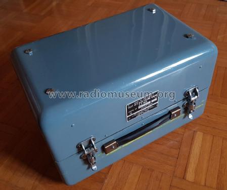
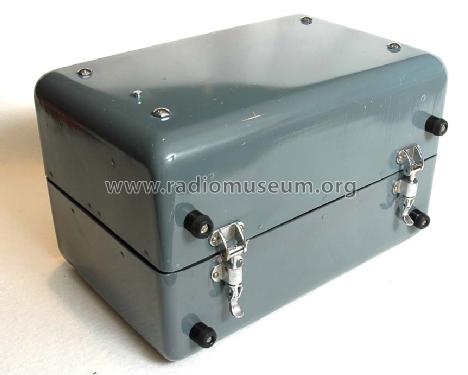
- Modèle de table profil bas (grand modèle).
- Dimensions (LHP)
- 255 x 295 x 370 mm / 10 x 11.6 x 14.6 inch
- Remarques
-
Static and Dynamic Characteristic (Mutual Conductance (mA/V))
Anode Volts: 20, 40, 60, 75, 90, 100, 150, 200, 250, 300, 400V
Screen Volts: 20, 40, 60, 75, 90, 100, 125, 150, 200, 250, 300V
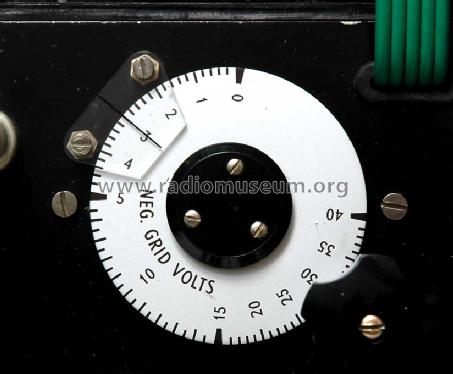
Neg. Grid Volts: 0 / -40V adjustable
Anode Current: 0 / 90mA & 0 / 10mA
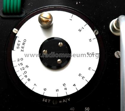
Set mA/V: 1, 20mA/V slop control
Mains Voltage Selector: 110, 180, 200, 220, 240V & -5 / 0 / +5 / +10V
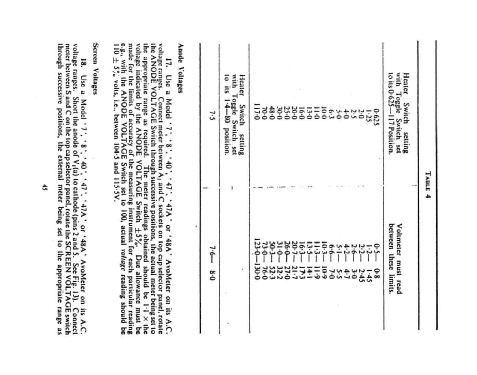
Heater Volts Switch 0,625 -117 position:
0,625 /1,25/ 2,0/ 2,5/ 4/ 5/ 6,3/ 10/ 11/ 13/ 16/ 20/ 25/ 30/ 48/ 70/ 117V
Heater Volts Switch 1,4 - 80 position
1,4/ 3/ 4,5/ 5,7/ 12,6/ 15/ 18/ 23/ 28/ 35/ 45/ 55/ 80V
- Poids net
- 11 kg / 24 lb 3.7 oz (24.229 lb)
- Source
- -- Original-techn. papers.
- Schémathèque (1)
- - - Data from my own collection
- Auteur
- Modèle crée par Hernani Capela. Voir les propositions de modification pour les contributeurs supplémentaires.
- D'autres Modèles
-
Vous pourrez trouver sous ce lien 82 modèles d'appareils, 79 avec des images et 41 avec des schémas.
Tous les appareils de Avo (Brand), Automatic Coil Winder and Electrical Equipment Co., Avo Ltd; London
Collections
Le modèle Test Set Electronic Valve fait partie des collections des membres suivants.
Contributions du forum pour ce modèle: Avo Brand, Automatic: Test Set Electronic Valve C.T.160
Discussions: 1 | Publications: 3
Dear members,
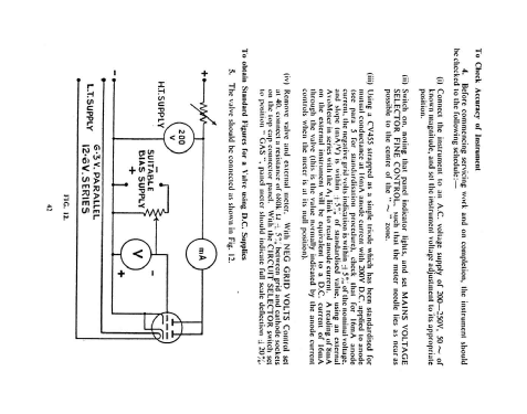
For a few days I'm trying to calibrate my AVO CT160 valve tester. I downloaded all the mauals and articles I could find, read the calibration parts several times. Did the calibration step by step. I checked all the resistors in the instrument (up till now I didn't check the capacitors and potmeters). Replaced the calibration resistors R3 and R4. And last but not least I made a calibration tube (ECL80) in the way it is described in the AVO manual. Checking the instrument with my new made calibration tube I found out that on the low end the Ia measurements from the AVO is a little to high (10%). In the middel it is oke and with higher Ia settings values from the AVO are lower (15%) than expected. Gm measurement is fine. Anyone who has experience with calibration of a AVO CT160? A little help is appreciated.
Regards,
Paul
Pièces jointes
- My AVO CT160 (91 KB)
Paul Cornelissen, 03.Nov.08
