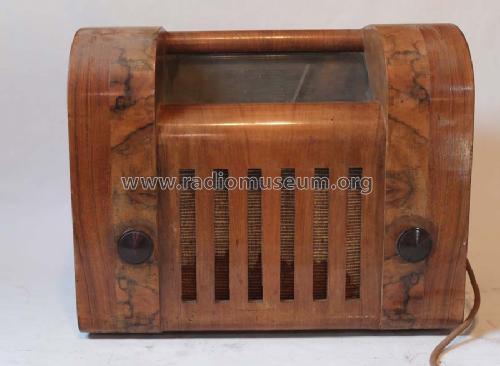
4W65H Holz
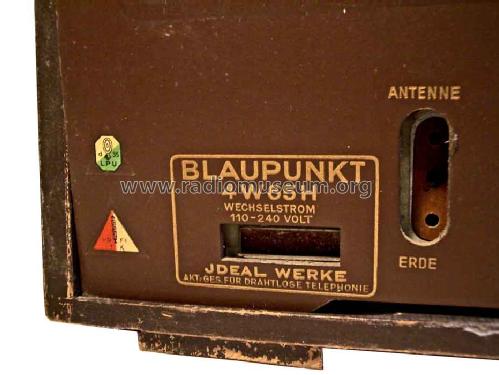
Blaupunkt (Ideal), Berlin, später Hildesheim
- Hersteller / Marke
- Blaupunkt (Ideal), Berlin, später Hildesheim
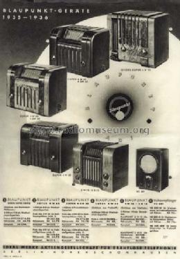
- Jahr
- 1935/1936
- Kategorie
- Rundfunkempfänger (Radio - oder Tuner nach WW2)
- Radiomuseum.org ID
- 537
-
- anderer Name: Ideal-Radiotelephon- und App-fabr. || Ideal-Werke AG; Berlin (ab 1934)
- Marke: Rotstern


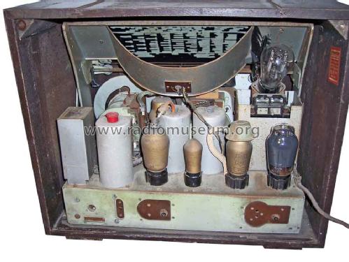


Guter Erhaltungszustand, unrestauriert.
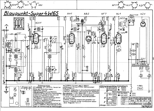
Klicken Sie auf den Schaltplanausschnitt, um diesen kostenlos als Dokument anzufordern.
- Anzahl Röhren
- 6
- Hauptprinzip
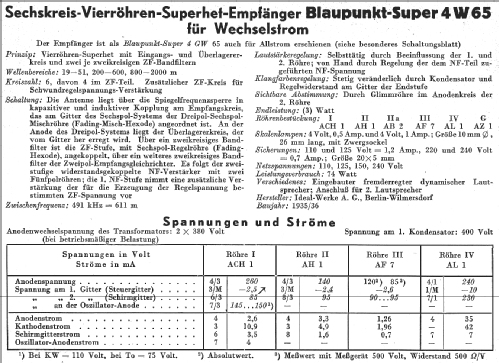
- Superhet allgemein; ZF/IF 491 kHz
- Anzahl Kreise
- 6 Kreis(e) AM
- Wellenbereiche
- Langwelle, Mittelwelle und Kurzwelle.
- Betriebsart / Volt
- Wechselstromspeisung / 110; 125; 220; 240 Volt
- Lautsprecher
- Dynamischer LS, mit Erregerspule (elektrodynamisch)
- Belastbarkeit / Leistung
- 3 W (Qualität unbekannt)
- Material
- Gerät mit Holzgehäuse
- von Radiomuseum.org
- Modell: 4W65H [Holz] - Blaupunkt Ideal, Berlin,
- Form
- Tischgerät-gross, - Querformat (breiter als hoch oder quadratisch).
- Abmessungen (BHT)
- 464 x 385 x 285 mm / 18.3 x 15.2 x 11.2 inch
- Bemerkung
- Feldstärke-Anzeige
- Originalpreis
- 332.00 RM
- Datenherkunft
- Katalog Radio-Zentrale Alex v. Prohaska 1935/1936 / Radiokatalog Band 1, Ernst Erb
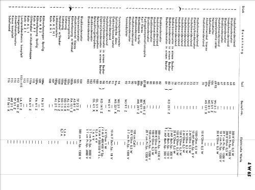
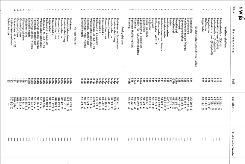
- Schaltungsnachweis
- Lange+Schenk+FS-Röhrenbestückung
- Bildnachweis
- Das Modell ist im «Radiokatalog» (Erb) abgebildet.
- Weitere Modelle
-
Hier finden Sie 3616 Modelle, davon 3308 mit Bildern und 2357 mit Schaltbildern.
Alle gelisteten Radios usw. von Blaupunkt (Ideal), Berlin, später Hildesheim
Sammlungen
Das Modell befindet sich in den Sammlungen folgender Mitglieder.
Forumsbeiträge zum Modell: Blaupunkt Ideal,: 4W65H
Threads: 2 | Posts: 5
Dear Rudolf,
I am waiting the new schematic. The wave switch of my device it is not compatible with any other schematic downloaded from Radiomuseum.
I want to thank you one more time and I am waiting the new schematic.
Best regards,
Ion Carabas
Ion Carabas, 11.May.11
Dear collegues,
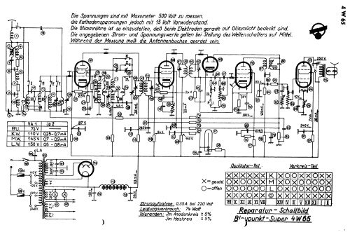
I am now working at an reconditioning of an radio device Blaupunkt 4W65 Holz. Having and reading the three schematics wich are posted on radiomuseum, I observed the followings, about the way of closing the contacts from wave changer comutator (interruptor).
A. No1 schematic
| 1 | 2 | 3 | 4 | 5 | 6 | 7 | 8 | 9 | 10 | 11 | 12 | 13 | 14 | |
| Kurz | x | x | x | x | x | x | x | x | x | x | x | |||
| Mittel | x | x | x | x | x | x | ||||||||
| Long | x | x | ||||||||||||
| Ta | x | x | x | x | x | x | x | x | x | x | x | x | x |
No2 Schematic
| 1 | 2 | 3 | 4 | 5 | 6 | 7 | 8 | 9 | 10 | 11 | 12 | 13 | 14 | |
| Kurz | x | x | x | |||||||||||
| Mittel | x | x | x | x | x | x | x | x | ||||||
| Long | x | x | x | x | x | x | x | x | x | x | x | x | ||
| Ta | x |
No3 Schematic (identical with second schematic)
| 1 | 2 | 3 | 4 | 5 | 6 | 7 | 8 | 9 | 10 | 11 | 12 | 13 | 14 | |
| Kurz | x | x | x | |||||||||||
| Mittel | x | x | x | x | x | x | x | x | ||||||
| Long | x | x | x | x | x | x | x | x | x | x | x | x | ||
| Ta | x |
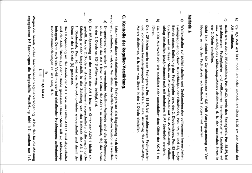
Wich one from the schematics described above represents the reality?
B. The radio device Blaupunkt 4W65H is equipped, instead if magic eye with an tube with neon OSRAM GJR 3. Can someone tell me wich are the alimentation tensions required for function and how are made the conections at the socle?
In the 3 schematics that I mentioned above , this condenser is coupled different (reffered to the condenser 0,2 Mf.)
Ion Carabas, 10.May.11