4W65H Holz
Blaupunkt (Ideal), Berlin, später Hildesheim
- Pays
- Allemagne
- Fabricant / Marque
- Blaupunkt (Ideal), Berlin, später Hildesheim
- Année
- 1935/1936
- Catégorie
- Radio - ou tuner d'après la guerre 1939-45
- Radiomuseum.org ID
- 537
-
- alternative name: Ideal-Radiotelephon- und App-fabr. || Ideal-Werke AG; Berlin (ab 1934)
- Brand: Rotstern
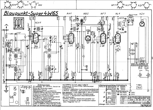
Cliquez sur la vignette du schéma pour le demander en tant que document gratuit.
- No. de tubes
- 6
- Principe général
- Super hétérodyne (en général); FI/IF 491 kHz
- Circuits accordés
- 6 Circuits MA (AM)
- Gammes d'ondes
- PO, GO et OC
- Tension / type courant
- Alimentation Courant Alternatif (CA) / 110; 125; 220; 240 Volt
- Haut-parleur
- HP dynamique à électro-aimant (électrodynamique)
- Puissance de sortie
- 3 W (qualité inconnue)
- Matière
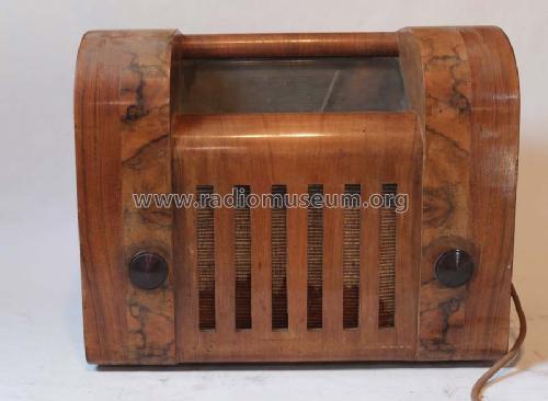
- Boitier en bois
- De Radiomuseum.org
- Modèle: 4W65H [Holz] - Blaupunkt Ideal, Berlin,
- Forme
- Modèle de table profil bas (grand modèle).
- Dimensions (LHP)
- 464 x 385 x 285 mm / 18.3 x 15.2 x 11.2 inch
- Remarques
- Feldstärke-Anzeige
- Prix de mise sur le marché
- 332.00 RM
- Source
- Katalog Radio-Zentrale Alex v. Prohaska 1935/1936 / Radiokatalog Band 1, Ernst Erb
- Source du schéma
- Lange+Schenk+FS-Röhrenbestückung
- Index des illustrations
- Das Modell ist im «Radiokatalog» (Erb) abgebildet.
- D'autres Modèles
-
Vous pourrez trouver sous ce lien 3616 modèles d'appareils, 3308 avec des images et 2357 avec des schémas.
Tous les appareils de Blaupunkt (Ideal), Berlin, später Hildesheim
Collections
Le modèle fait partie des collections des membres suivants.
Contributions du forum pour ce modèle: Blaupunkt Ideal,: 4W65H
Discussions: 2 | Publications: 5
Dear Rudolf,
I am waiting the new schematic. The wave switch of my device it is not compatible with any other schematic downloaded from Radiomuseum.
I want to thank you one more time and I am waiting the new schematic.
Best regards,
Ion Carabas
Ion Carabas, 11.May.11
Dear collegues,
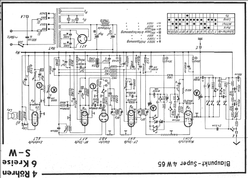
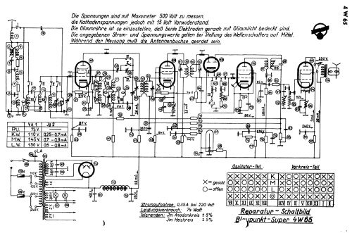
I am now working at an reconditioning of an radio device Blaupunkt 4W65 Holz. Having and reading the three schematics wich are posted on radiomuseum, I observed the followings, about the way of closing the contacts from wave changer comutator (interruptor).
A. No1 schematic
| 1 | 2 | 3 | 4 | 5 | 6 | 7 | 8 | 9 | 10 | 11 | 12 | 13 | 14 | |
| Kurz | x | x | x | x | x | x | x | x | x | x | x | |||
| Mittel | x | x | x | x | x | x | ||||||||
| Long | x | x | ||||||||||||
| Ta | x | x | x | x | x | x | x | x | x | x | x | x | x |
No2 Schematic
| 1 | 2 | 3 | 4 | 5 | 6 | 7 | 8 | 9 | 10 | 11 | 12 | 13 | 14 | |
| Kurz | x | x | x | |||||||||||
| Mittel | x | x | x | x | x | x | x | x | ||||||
| Long | x | x | x | x | x | x | x | x | x | x | x | x | ||
| Ta | x |
No3 Schematic (identical with second schematic)
| 1 | 2 | 3 | 4 | 5 | 6 | 7 | 8 | 9 | 10 | 11 | 12 | 13 | 14 | |
| Kurz | x | x | x | |||||||||||
| Mittel | x | x | x | x | x | x | x | x | ||||||
| Long | x | x | x | x | x | x | x | x | x | x | x | x | ||
| Ta | x |
Wich one from the schematics described above represents the reality?
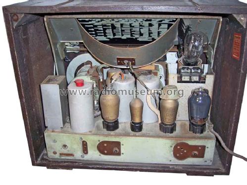
B. The radio device Blaupunkt 4W65H is equipped, instead if magic eye with an tube with neon OSRAM GJR 3. Can someone tell me wich are the alimentation tensions required for function and how are made the conections at the socle?
In the 3 schematics that I mentioned above , this condenser is coupled different (reffered to the condenser 0,2 Mf.)
Ion Carabas, 10.May.11


