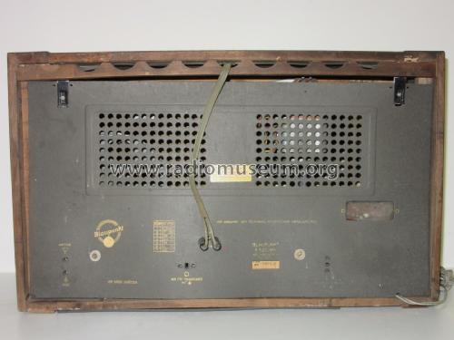
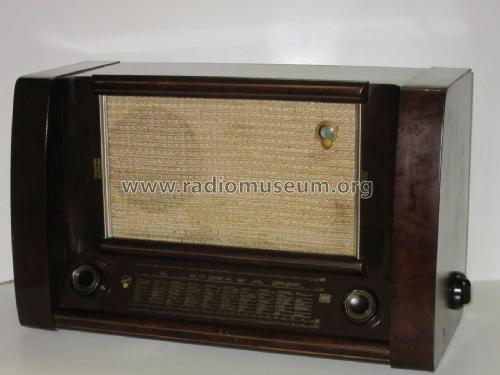
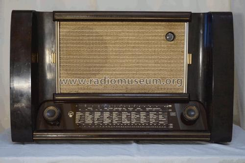
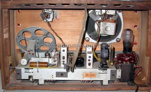
- Country
- Germany
- Manufacturer / Brand
- Blaupunkt (Ideal), Berlin, später Hildesheim
- Year
- 1952/1953
- Category
- Broadcast Receiver - or past WW2 Tuner
- Radiomuseum.org ID
- 19193
-
- alternative name: Ideal-Radiotelephon- und App-fabr. || Ideal-Werke AG; Berlin (ab 1934)
- Brand: Rotstern
Click on the schematic thumbnail to request the schematic as a free document.
- Number of Tubes
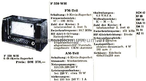
- 7
- Main principle
- Superheterodyne (common); ZF/IF 473/10700 kHz; Reflex
- Tuned circuits
- 6 AM circuit(s) 8 FM circuit(s)
- Wave bands
- Broadcast, Long Wave, Short Wave plus FM or UHF.
- Power type and voltage
- Alternating Current supply (AC) / 110; 125; 220 Volt
- Loudspeaker
- Electro Magnetic Dynamic LS (moving-coil with field excitation coil) / Ø 19 cm = 7.5 inch
- Power out
- 4 W (unknown quality)
- Material
- Wooden case
- from Radiomuseum.org
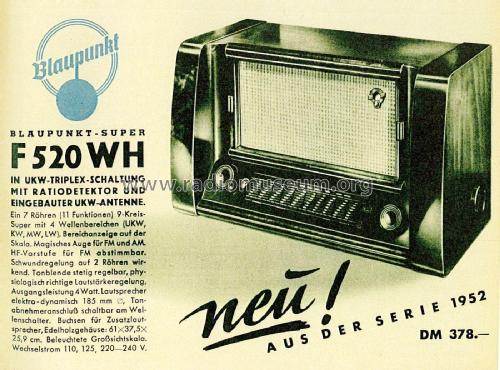
- Model: F520WH - Blaupunkt Ideal, Berlin,
- Shape
- Tablemodel, low profile (big size).
- Dimensions (WHD)
- 610 x 375 x 259 mm / 24 x 14.8 x 10.2 inch
- Notes
- EF80 arbeitet als UKW HF-, ZF- und NF-Stufe (Reflexschaltung) Bei UKW Variometerabstimmung, bei den AM- Bereichen Abstimmung mit Drehkondensator.
- Price in first year of sale
- 378.00 DM
- External source of data
- Erb
- Source of data
- Kat.d.Rundf.GrossH.1952/53
- Other Models
-
Here you find 3593 models, 3282 with images and 2332 with schematics for wireless sets etc. In French: TSF for Télégraphie sans fil.
All listed radios etc. from Blaupunkt (Ideal), Berlin, später Hildesheim
Collections
The model is part of the collections of the following members.
Forum contributions about this model: Blaupunkt Ideal,: F520WH
Threads: 1 | Posts: 2
Hallo zusammen,
ich stehe gerade richtig auf dem "Schlauch". Ich habe den Blaupunkt F520WH am Flohmarkt gekauft.
Bei der Reparatur habe ich festegstellt, dass der Netztrafafo defekt ist und bereits alle Drähte abgelötet waren. Nun habe ich den Trafo durch einen anderen Universaltrafo ersetzt. Ich verwende einen Trafo mit sek. 2 x 250VAC (hoffentlich der richtige Wert, da im Schlatbild keinerlei Spannungen angegeben sind).
Im Schaltbild ist keine Mittealanzapfung des Trafos zu sehen. Ich bin mir jedoch relaiv sicher, dass die Masse nicht über die zwei 5nF Kondensatoren erzeugt wird. Wenn ich die Mittelanzapfung des Trafos auf die Chasismasse lege habe ich einen deutlichen Brummton - auch bei voll zurückgedrehter Lautstärke. Vermutlich muss die Mittelanzapfung des Trafio an einem Widerstand angeschlssen werden.
Hat hier jemand einen Tip für mich.
Viele Grüße
Jörg

Jörg Ochs, 06.Jan.23


