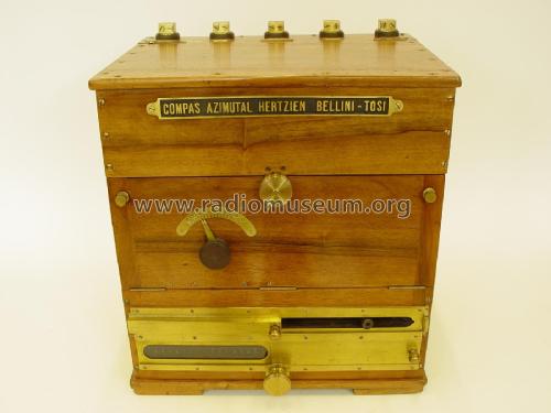
Compas Azimutal Hertzien Bellini-Tosi - B-T Radio Direction Finder
Ducretet (-Thomson; avant: Fernand Ducretet et Ernest Roger etc.); Paris
- Land
- Frankreich / France
- Hersteller / Marke
- Ducretet (-Thomson; avant: Fernand Ducretet et Ernest Roger etc.); Paris
- Jahr
- 1913 ??

- Kategorie
- Detektorempfänger (Kristall oder Diode, ohne Röhre/Transistoren)
- Radiomuseum.org ID
- 298273
-
- anderer Name: SED
- Hauptprinzip
- Detektion ohne aktive Elemente, solid state
- Wellenbereiche
- Langwellenempfänger und/oder Längstwellen-Empfänger.
- Betriebsart / Volt
- Keine Stromversorgung
- Lautsprecher
- - Für Kopfhörer oder NF-Verstärker
- Material
- Gerät mit Holzgehäuse
- von Radiomuseum.org
- Modell: Compas Azimutal Hertzien Bellini-Tosi - B-T Radio Direction Finder - Ducretet -Thomson; avant:
- Form
- Tischgerät, Truhenform, meist mit Deckel (NICHT Schrägpult).
- Abmessungen (BHT)
- 430 x 470 x 370 mm / 16.9 x 18.5 x 14.6 inch
- Bemerkung
-
A Bellini-Tosi direction finder (B-T or BTDF) is a type of radio direction finder (RDF), which determines the direction to, or bearing of, a radio transmitter. Earlier RDF systems used very large rotating loop antennae, which the B-T system replaced with two fixed antennae and a small rotating loop, known as a radiogoniometer. This made RDF much more practical, especially on large vehicles like ships or when using very long wavelengths that demand large antennae.
BTDF was invented by a pair of Italian officers in the early 1900s, and is sometimes known as a Marconi-Bellini-Tosi after they joined forces with the Marconi Company in 1912. BTDF was the most prevalent form of naval direction finding from the 1920s to well into the 1980s, and were a used as a major part of early long-distance air navigation systems from the 1930s until after World War II. BTDF systems were also widely used for military signals intelligence gathering.
The received signal is re-radiated by forming a loop with multiple winds of wire. Using two loop antennae arranged at right angles and two sets of these small wire coils arranged the same way, the directional properties of the original radio signal can be re-created. Direction finding could then be carried out with a conventional loop antenna placed in the center of these two stators (or field coils); the rotating loop was known as the rotor (or sense coil).
Since the field coils were connected to the antennae electrically, they could be placed anywhere, and their size was independent of the wavelength. This meant that RDF could now be performed on longest wavelengths with ease, using antennae of any size. For longwave use, the two crossed antennae could be easily built by running four wires from a single mast to the ground to form triangular shapes. When used with shorter wavelengths, the system of two crossed loop antennae proved to be more mechanically robust than a single rotating one. They had the added advantage that the antennae could be placed almost anywhere; earlier systems often included some sort of remote operation through a mechanical linkage, but this limited the placement of the antenna or receiver room.
The pair sold the patents to the Marconi Company in February 1912, and Bellini joined the company to continue development there.
- Nettogewicht
- 35 kg / 77 lb 1.5 oz (77.093 lb)
- Autor
- Modellseite von Musée des Radios Museum angelegt. Siehe bei "Änderungsvorschlag" für weitere Mitarbeit.
- Weitere Modelle
-
Hier finden Sie 657 Modelle, davon 523 mit Bildern und 286 mit Schaltbildern.
Alle gelisteten Radios usw. von Ducretet (-Thomson; avant: Fernand Ducretet et Ernest Roger etc.); Paris
Sammlungen
Das Modell Compas Azimutal Hertzien Bellini-Tosi - B-T Radio Direction Finder befindet sich in den Sammlungen folgender Mitglieder.

