12 table model
Ferguson (in the United States - see text)
- Land
- USA
- Hersteller / Marke
- Ferguson (in the United States - see text)
- Jahr
- 1926/1927
- Kategorie
- Rundfunkempfänger (Radio - oder Tuner nach WW2)
- Radiomuseum.org ID
- 40495
-
- anderer Name: Ferguson Co., J.B. || Ferguson Radio Corp. || Ferguson Radio &Television Co., Inc.


Klicken Sie auf den Schaltplanausschnitt, um diesen kostenlos als Dokument anzufordern.
- Anzahl Röhren
- 6
- Röhren
- Hauptprinzip
- Geradeaus allg. (mit oder ohne Rückk.)
- Wellenbereiche
- Mittelwelle, keine anderen.
- Betriebsart / Volt
- Akku und/oder Batterie
- Lautsprecher
- - Dieses Modell benötigt externe(n) Lautsprecher.
- Material
- Gerät mit Holzgehäuse
- von Radiomuseum.org
- Modell: 12 table model - Ferguson in the United States
- Form
- Tischmodell, Zusatz nicht bekannt - allgemein.
- Bemerkung
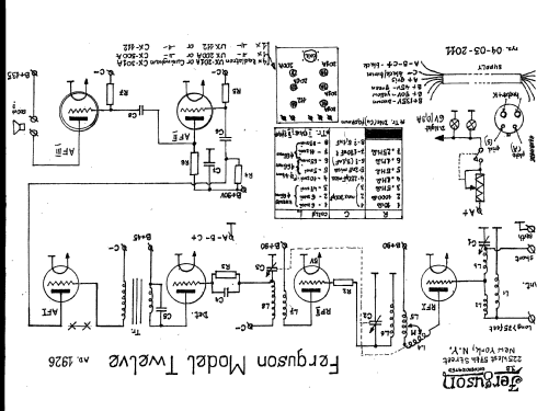
- Two dials (primary tuning control knobs)
- Originalpreis
- 75.00 $
- Datenherkunft extern
- Ernst Erb
- Datenherkunft
- Radio Collector`s Guide 1921-1932
- Literaturnachweis
- Collector's Guide to Antique Radios 4. Edition
- Weitere Modelle
-
Hier finden Sie 66 Modelle, davon 16 mit Bildern und 39 mit Schaltbildern.
Alle gelisteten Radios usw. von Ferguson (in the United States - see text)
Forumsbeiträge zum Modell: Ferguson in the: 12 table model
Threads: 1 | Posts: 3
Hello,
I own a Ferguson - 12, but I do not know if it is the old or the new one. I have unmounted it from the case for drawing schematic and doing some minor repairs.
It has 3 AF stages. The coupling between 1-2 and 2-3 are RC. The coupling between detector and 1st AF is by a transformer of the brand “Silver - Marshall”. Because the shape of transformer mounting and connections I think it could not to be the original.
In addition, I need some information about DC supply:
The are four +B sources ( detector plate, RF , AF(1-2) stages and power stage. May be 22.5 for detector, 135 for power and ¿ what for AF and RF ?
There is -C for grid returns of the 3 AF stages, the same for all three, two of them 201A and the last one of 112A type. For both tubes -C would be -9 volts if +B were 135. But 201A and 112A have a diferent DC wire.
The reostat is only conected to the RF amplifier (2 tubes). Then, all other tubes should work at battery voltage ( 6 or more volts) ?
Finally, I suppose that -B is connected to ground. Ins this case, if +A battery is connected to -B, the grid return of AF would be to +A, not usual, I think. The grid of detector tube returns also to +A, but it is a 200A, and for this also seems to be wrong.
I will be thankful for much any information or suggestion on this subject.
Felix Corrochano, 13.Jan.11