12 table model
Ferguson (in the United States - see text)
- País
- Estados Unidos
- Fabricante / Marca
- Ferguson (in the United States - see text)
- Año
- 1926/1927
- Categoría
- Radio - o Sintonizador pasado WW2
- Radiomuseum.org ID
- 40495
-
- alternative name: Ferguson Co., J.B. || Ferguson Radio Corp. || Ferguson Radio &Television Co., Inc.
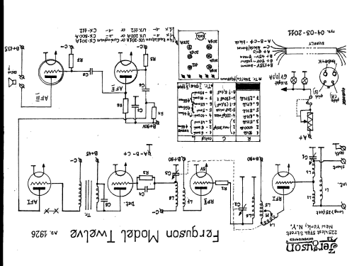


Haga clic en la miniatura esquemática para solicitarlo como documento gratuito.
- Numero de valvulas
- 6
- Válvulas
- Principio principal
- RFS (Radio Frecuencia Sintonizada) en general
- Gama de ondas
- OM (onda media) solamente
- Tensión de funcionamiento
- Baterías recargables o pilas
- Altavoz
- - Este modelo usa altavoz exterior (1 o más).
- Material
- Madera
- de Radiomuseum.org
- Modelo: 12 table model - Ferguson in the United States
- Forma
- Sobremesa de cualquier forma, detalles no conocidos.
- Anotaciones
- Two dials (primary tuning control knobs)
- Precio durante el primer año
- 75.00 $
- Ext. procedencia de los datos
- Ernst Erb
- Procedencia de los datos
- Radio Collector`s Guide 1921-1932
- Mencionado en
- Collector's Guide to Antique Radios 4. Edition
- Otros modelos
-
Donde encontrará 66 modelos, 16 con imágenes y 39 con esquemas.
Ir al listado general de Ferguson (in the United States - see text)
Colecciones
El modelo 12 es parte de las colecciones de los siguientes miembros.
Contribuciones en el Foro acerca de este modelo: Ferguson in the: 12 table model
Hilos: 1 | Mensajes: 3
Hello,
I own a Ferguson - 12, but I do not know if it is the old or the new one. I have unmounted it from the case for drawing schematic and doing some minor repairs.
It has 3 AF stages. The coupling between 1-2 and 2-3 are RC. The coupling between detector and 1st AF is by a transformer of the brand “Silver - Marshall”. Because the shape of transformer mounting and connections I think it could not to be the original.
In addition, I need some information about DC supply:
The are four +B sources ( detector plate, RF , AF(1-2) stages and power stage. May be 22.5 for detector, 135 for power and ¿ what for AF and RF ?
There is -C for grid returns of the 3 AF stages, the same for all three, two of them 201A and the last one of 112A type. For both tubes -C would be -9 volts if +B were 135. But 201A and 112A have a diferent DC wire.
The reostat is only conected to the RF amplifier (2 tubes). Then, all other tubes should work at battery voltage ( 6 or more volts) ?
Finally, I suppose that -B is connected to ground. Ins this case, if +A battery is connected to -B, the grid return of AF would be to +A, not usual, I think. The grid of detector tube returns also to +A, but it is a 200A, and for this also seems to be wrong.
I will be thankful for much any information or suggestion on this subject.
Felix Corrochano, 13.Jan.11