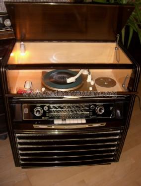
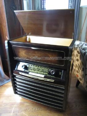
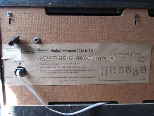
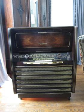
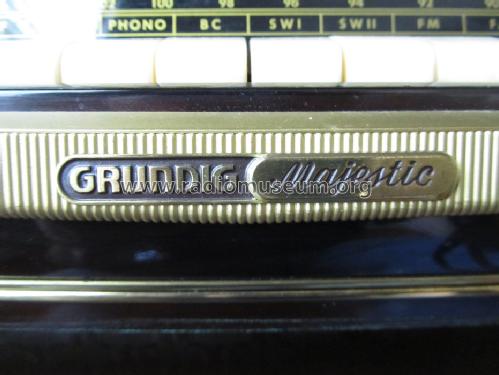
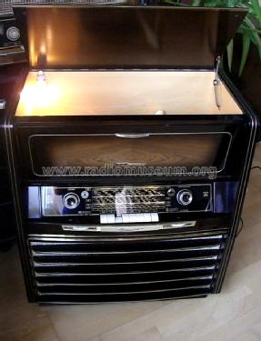
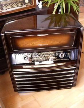
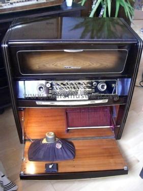
Majestic Musical Instrument 7063W/3D
Grundig (Radio-Vertrieb, RVF, Radiowerke); Fürth/Bayern
- Pays
- Allemagne
- Fabricant / Marque
- Grundig (Radio-Vertrieb, RVF, Radiowerke); Fürth/Bayern
- Année
- 1955/1956
- Catégorie
- Radio - ou tuner d'après la guerre 1939-45
- Radiomuseum.org ID
- 223420
-
- alternative name: Grundig Portugal || Grundig USA / Lextronix
- No. de tubes
- 6
- No. de transistors
- Semi-conducteurs
- B250C100
- Principe général
- Super hétérodyne (en général); FI/IF 468/10700 kHz
- Circuits accordés
- 8 Circuits MA (AM) 13 Circuits MF (FM)
- Gammes d'ondes
- PO, 2 x OC et FM
- Particularités
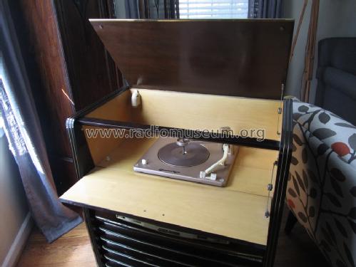
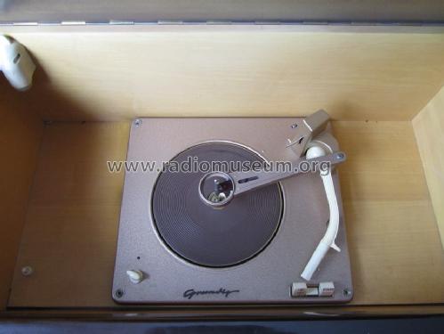
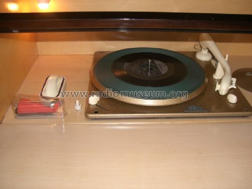
- Tourne disque avec changeur; Télécommande par HF ou fil
- Tension / type courant
- Alimentation Courant Alternatif (CA) / 110; 125; 160; 220 Volt
- Haut-parleur
- 4 HP
- Puissance de sortie
- 4 W (qualité inconnue)
- Matière
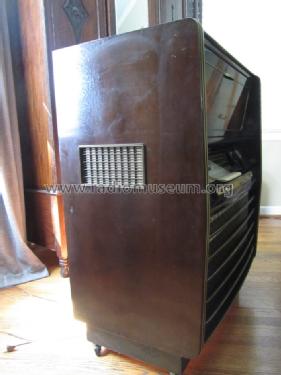
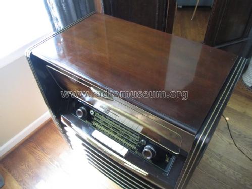
- Boitier en bois
- De Radiomuseum.org
- Modèle: Majestic Musical Instrument 7063W/3D - Grundig Radio-Vertrieb, RVF,
- Forme
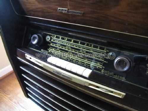
- Console avec des boutons-poussoirs
- Dimensions (LHP)
- 720 x 854 x 415 mm / 28.3 x 33.6 x 16.3 inch
- Remarques
-
Chassis = 3055W/3D or 3055W/3D-Ph. Grundig Export version of 7063W/3D for North America (or US only), sold by Majestic, USA. See also Musikschrank 7063WF/3D, a most similar domestic version.
FM: 88 to 108 MHz
SW1: 5.9 to 13 MHz
SW2: 13 to 23 MHz
BC: 510 to 1610 kHz, dial with CD (Civil Defense) marks (see also Conelrad)
- Poids net
- 44.2 kg / 97 lb 5.7 oz (97.357 lb)
- Source extérieure
- Member David S. Schulman
- Auteur
- Modèle crée par Ernst Erb. Voir les propositions de modification pour les contributeurs supplémentaires.
- D'autres Modèles
-
Vous pourrez trouver sous ce lien 6240 modèles d'appareils, 5481 avec des images et 4238 avec des schémas.
Tous les appareils de Grundig (Radio-Vertrieb, RVF, Radiowerke); Fürth/Bayern
Collections
Le modèle Majestic Musical Instrument fait partie des collections des membres suivants.
Contributions du forum pour ce modèle: Grundig Radio-: Majestic Musical Instrument 7063W/3D
Discussions: 2 | Publications: 11
The first photo shows what I believe to be the volume control on the schematic for this model. The problem that I am having is that a single connection with 3 components has become detached from the edge of the wafer assembly on that control. The thing that is baffling, is that the wafer does not appear to have any type of lead or electrical connection coming off of it where that connection would have been soldered to. Could it have been a common area for that connection with no electrical significance? Or is there a small trace somewhere on that wafer that would served as the connection? I can't see it and it's not visible in the photos. The schematic does show what I believe to be the components that are connected to the volume control, which are the ones that make that single connection which appears to have broken away; the 25n cap, 15k resistor and .2M resistor. Does anyone have some experience with this this control and how this may work? The last volume control photo is the front side of the component.
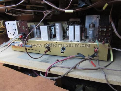
Also, a second question the last photo shows a couple of blue capacitors. These are throughout the set. I'm in the process of replacing all the wax and paper caps and wanted to know if these should be replaced along with the others, or if they are reliable enough to leave in the radio? Thanks in advance for your assistance.
David
Pièces jointes
- Volume control schematic (45 KB)
- Volume control broken wafer edge side 1 (91 KB)
- Volume control broken wafer edge side 1 close up (60 KB)
- Volume control broken wafer edge side 2 close up (49 KB)
- Blue capacitor (152 KB)
David Schulman, 29.Mar.13
I'm restoring a German set that I have and found what I believe to be an electrolytic cap that needs replacing. From what I can tell, it's 20uf @ 35 / 40 V. However, what I can't tell, is what the positive and negative leads are. They are marked 1 & 2. See attached photo. I'm not familiar with this designation, can anyone help? It is sincerely appreciated.
Pièces jointes
- 20 uf Electrolytic (133 KB)
David Schulman, 25.Mar.13