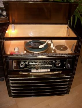
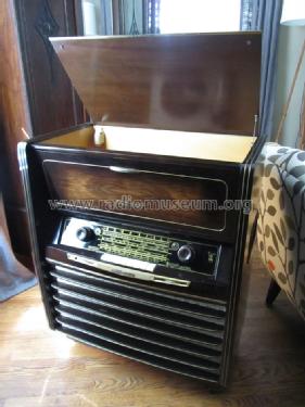
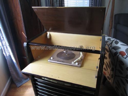
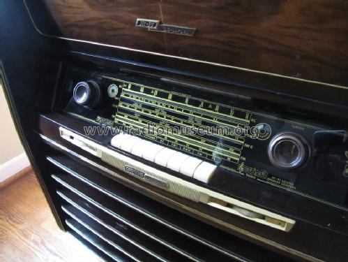
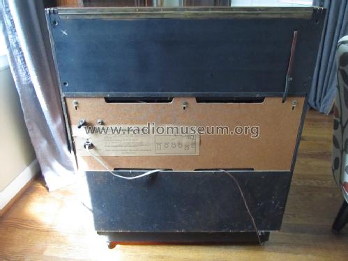
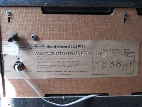
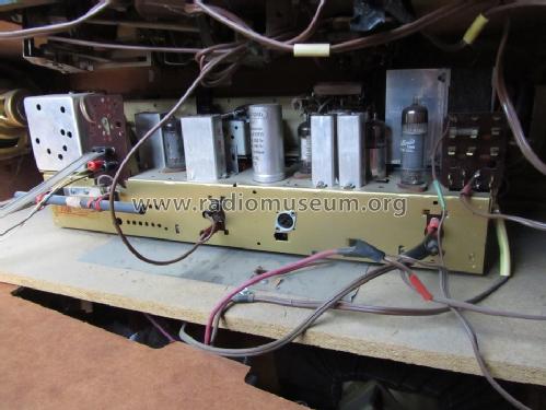
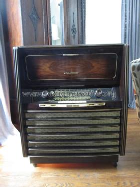
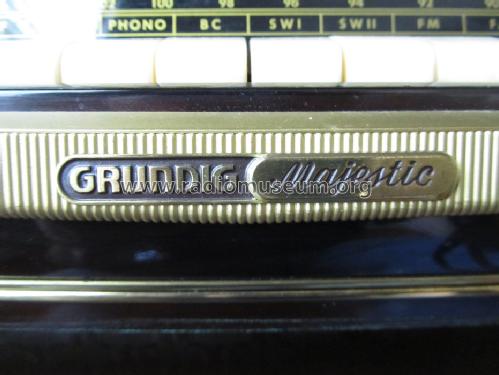
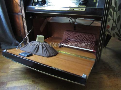
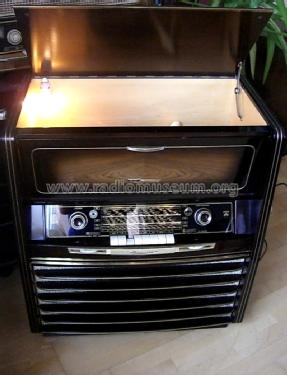
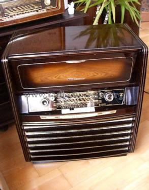
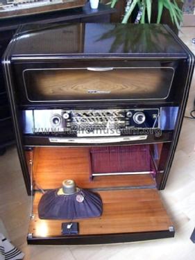
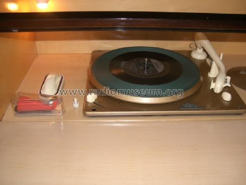
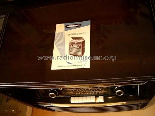
Majestic Musical Instrument 7063W/3D
Grundig (Radio-Vertrieb, RVF, Radiowerke); Fürth/Bayern
- País
- Alemania
- Fabricante / Marca
- Grundig (Radio-Vertrieb, RVF, Radiowerke); Fürth/Bayern
- Año
- 1955/1956
- Categoría
- Radio - o Sintonizador pasado WW2
- Radiomuseum.org ID
- 223420
-
- alternative name: Grundig Portugal || Grundig USA / Lextronix
- Numero de valvulas
- 6
- Numero de transistores
- Semiconductores
- B250C100
- Principio principal
- Superheterodino en general; ZF/IF 468/10700 kHz
- Número de circuitos sintonía
- 8 Circuíto(s) AM 13 Circuíto(s) FM
- Gama de ondas
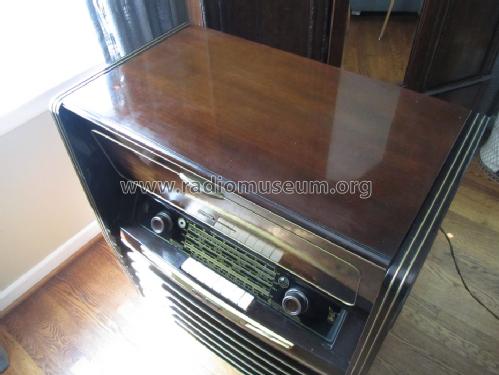
- OM, dos OC y FM
- Especialidades
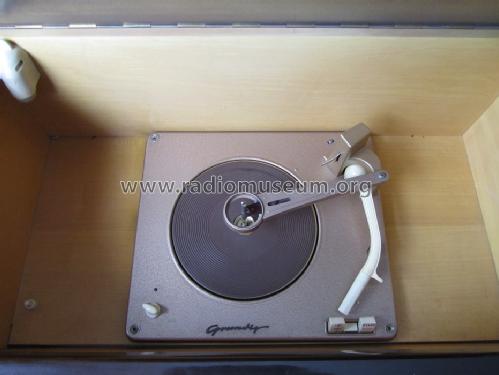
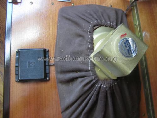
- Tocadiscos con cambiador autom.; Remote Control (with wire or wireless)
- Tensión de funcionamiento
- Red: Corriente alterna (CA, Inglés = AC) / 110; 125; 160; 220 Volt
- Altavoz
- 4 Altavoces
- Potencia de salida
- 4 W (unknown quality)
- Material
- Madera
- de Radiomuseum.org
- Modelo: Majestic Musical Instrument 7063W/3D - Grundig Radio-Vertrieb, RVF,
- Forma
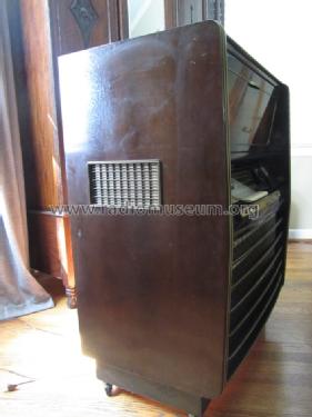
- Consola con botonera.
- Ancho, altura, profundidad
- 720 x 854 x 415 mm / 28.3 x 33.6 x 16.3 inch
- Anotaciones
-
Chassis = 3055W/3D or 3055W/3D-Ph. Grundig Export version of 7063W/3D for North America (or US only), sold by Majestic, USA. See also Musikschrank 7063WF/3D, a most similar domestic version.
FM: 88 to 108 MHz
SW1: 5.9 to 13 MHz
SW2: 13 to 23 MHz
BC: 510 to 1610 kHz, dial with CD (Civil Defense) marks (see also Conelrad)
- Peso neto
- 44.2 kg / 97 lb 5.7 oz (97.357 lb)
- Ext. procedencia de los datos
- Member David S. Schulman
- Autor
- Modelo creado por Ernst Erb. Ver en "Modificar Ficha" los participantes posteriores.
- Otros modelos
-
Donde encontrará 6235 modelos, 5474 con imágenes y 4233 con esquemas.
Ir al listado general de Grundig (Radio-Vertrieb, RVF, Radiowerke); Fürth/Bayern
Colecciones
El modelo Majestic Musical Instrument es parte de las colecciones de los siguientes miembros.
Contribuciones en el Foro acerca de este modelo: Grundig Radio-: Majestic Musical Instrument 7063W/3D
Hilos: 2 | Mensajes: 11
The first photo shows what I believe to be the volume control on the schematic for this model. The problem that I am having is that a single connection with 3 components has become detached from the edge of the wafer assembly on that control. The thing that is baffling, is that the wafer does not appear to have any type of lead or electrical connection coming off of it where that connection would have been soldered to. Could it have been a common area for that connection with no electrical significance? Or is there a small trace somewhere on that wafer that would served as the connection? I can't see it and it's not visible in the photos. The schematic does show what I believe to be the components that are connected to the volume control, which are the ones that make that single connection which appears to have broken away; the 25n cap, 15k resistor and .2M resistor. Does anyone have some experience with this this control and how this may work? The last volume control photo is the front side of the component.
Also, a second question the last photo shows a couple of blue capacitors. These are throughout the set. I'm in the process of replacing all the wax and paper caps and wanted to know if these should be replaced along with the others, or if they are reliable enough to leave in the radio? Thanks in advance for your assistance.
David
Anexos
- Volume control schematic (45 KB)
- Volume control broken wafer edge side 1 (91 KB)
- Volume control broken wafer edge side 1 close up (60 KB)
- Volume control broken wafer edge side 2 close up (49 KB)
- Blue capacitor (152 KB)
David Schulman, 29.Mar.13
I'm restoring a German set that I have and found what I believe to be an electrolytic cap that needs replacing. From what I can tell, it's 20uf @ 35 / 40 V. However, what I can't tell, is what the positive and negative leads are. They are marked 1 & 2. See attached photo. I'm not familiar with this designation, can anyone help? It is sincerely appreciated.
Anexos
- 20 uf Electrolytic (133 KB)
David Schulman, 25.Mar.13
