Condenser Checker C-1
Heathkit (Brand), Heath Co.; Benton Harbor (MI)
- Produttore / Marca
- Heathkit (Brand), Heath Co.; Benton Harbor (MI)
- Anno
- 1948 ?
- Categoria
- Strumento da laboratorio
- Radiomuseum.org ID
- 80758
-
- alternative name: Heath Company


Ebay Nr. 170102025544 Bild bearbeitet.

Ebay Nr. 170102025544 Bild bearbeitet.

Heathkit C-1 ad in RadioNews May 1948 p102

Heathkit C-1 in June 1948 ad

Heathkit C-1 in actual use
Clicca sulla miniatura dello schema per richiederlo come documento gratuito.
- Numero di tubi
- 2
- Tensioni di funzionamento
- Alimentazione a corrente alternata (CA) / 105-125 Volt
- Radiomuseum.org
- Modello: Condenser Checker C-1 - Heathkit Brand, Heath Co.;
- Forma
- Soprammobile con qualsiasi forma (non saputo).
- Annotazioni
-
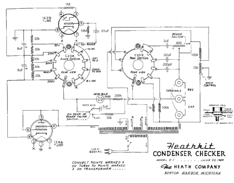
The is a modified version of the original schematic is for the Heathkit C-1 Condenser Checker, the modification replaced part numbers with actual component values. Please note that the network of 30k ohm resistors should drop voltages equally. The 20 VDC switch setting should per the schematic produce an actual voltage of 100 VDC. However, the actual voltage on a capacitor under test would be reduced by the voltage required by the neon lamp.
- Peso netto
- 4 lb (4 lb 0 oz) / 1.816 kg
- Prezzo nel primo anno
- 19.50 US$
- Fonte dei dati
- Radio News
- Bibliografia
- -- Schematic (Heathkit ads)
- Letteratura / Schemi (1)
- Chuck Penson: "Heathkit Test Equipment Products", page 2-01
- Autore
- Modello inviato da Bernd Pötzsch. Utilizzare "Proponi modifica" per inviare ulteriori dati.
- Altri modelli
-
In questo link sono elencati 718 modelli, di cui 701 con immagini e 507 con schemi.
Elenco delle radio e altri apparecchi della Heathkit (Brand), Heath Co.; Benton Harbor (MI)
Collezioni
Il modello Condenser Checker fa parte delle collezioni dei seguenti membri.
Discussioni nel forum su questo modello: Heathkit Brand,: Condenser Checker C-1
Argomenti: 1 | Articoli: 1
An electrolytic can be reformed in step-wise fashion. The neon bulb (below the eye tube) lights when the reforming current is about 2 mA or more. The reforming process starts with the voltage step switch set at the lowest voltage at which the neon bulb lights. As reforming progresses, the neon bulb will go out when reforming current drops below 2 mA. At that point the next higher voltage step can be selected until the capacitor shows full proper voltage on an external voltmeter. When the reforming process is complete, the tester's power is switched off and the step switch moved to the "R" position to quickly bring the voltage across the capacitor back to zero. The "R" setting places a 1000 ohm resistor across the test leads.
Rich Post, 31.Jan.22