Condenser Checker C-1
Heathkit (Brand), Heath Co.; Benton Harbor (MI)
- País
- Estados Unidos
- Fabricante / Marca
- Heathkit (Brand), Heath Co.; Benton Harbor (MI)
- Año
- 1948 ?
- Categoría
- Aparato de medida y servicio (Equipo de laboratorio).
- Radiomuseum.org ID
- 80758
-
- alternative name: Heath Company


Ebay Nr. 170102025544 Bild bearbeitet.

Ebay Nr. 170102025544 Bild bearbeitet.

Heathkit C-1 ad in RadioNews May 1948 p102

Heathkit C-1 in June 1948 ad

Heathkit C-1 in actual use
Haga clic en la miniatura esquemática para solicitarlo como documento gratuito.
- Numero de valvulas
- 2
- Tensión de funcionamiento
- Red: Corriente alterna (CA, Inglés = AC) / 105-125 Volt
- de Radiomuseum.org
- Modelo: Condenser Checker C-1 - Heathkit Brand, Heath Co.;
- Forma
- Sobremesa de cualquier forma, detalles no conocidos.
- Anotaciones
-
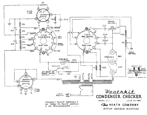
The is a modified version of the original schematic is for the Heathkit C-1 Condenser Checker, the modification replaced part numbers with actual component values. Please note that the network of 30k ohm resistors should drop voltages equally. The 20 VDC switch setting should per the schematic produce an actual voltage of 100 VDC. However, the actual voltage on a capacitor under test would be reduced by the voltage required by the neon lamp.
- Peso neto
- 4 lb (4 lb 0 oz) / 1.816 kg
- Precio durante el primer año
- 19.50 US$
- Procedencia de los datos
- Radio News
- Mencionado en
- -- Schematic (Heathkit ads)
- Documentación / Esquemas (1)
- Chuck Penson: "Heathkit Test Equipment Products", page 2-01
- Autor
- Modelo creado por Bernd Pötzsch. Ver en "Modificar Ficha" los participantes posteriores.
- Otros modelos
-
Donde encontrará 718 modelos, 701 con imágenes y 507 con esquemas.
Ir al listado general de Heathkit (Brand), Heath Co.; Benton Harbor (MI)
Colecciones
El modelo Condenser Checker es parte de las colecciones de los siguientes miembros.
Contribuciones en el Foro acerca de este modelo: Heathkit Brand,: Condenser Checker C-1
Hilos: 1 | Mensajes: 1
An electrolytic can be reformed in step-wise fashion. The neon bulb (below the eye tube) lights when the reforming current is about 2 mA or more. The reforming process starts with the voltage step switch set at the lowest voltage at which the neon bulb lights. As reforming progresses, the neon bulb will go out when reforming current drops below 2 mA. At that point the next higher voltage step can be selected until the capacitor shows full proper voltage on an external voltmeter. When the reforming process is complete, the tester's power is switched off and the step switch moved to the "R" position to quickly bring the voltage across the capacitor back to zero. The "R" setting places a 1000 ohm resistor across the test leads.
Rich Post, 31.Jan.22