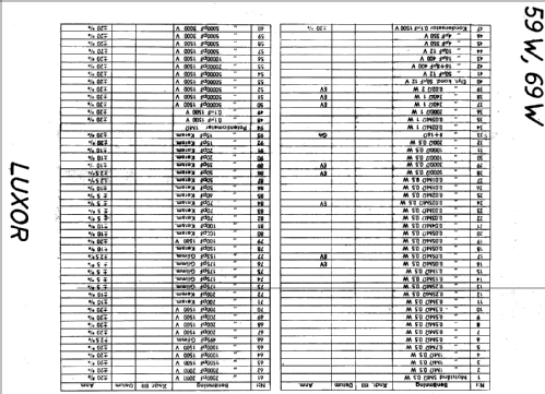
Diplomat 59W
Luxor Radio AB; Motala
- Paese
- Svezia
- Produttore / Marca
- Luxor Radio AB; Motala
- Anno
- 1945/1946
- Categoria
- Radio (o sintonizzatore del dopoguerra WW2)
- Radiomuseum.org ID
- 18201
-
- alternative name: Luxorita - voir Luxor Radio AB Suède (Sweden)
Clicca sulla miniatura dello schema per richiederlo come documento gratuito.
- Numero di tubi
- 8
- Principio generale
- Supereterodina (in generale)
- Gamme d'onda
- Onde medie (OM), lunghe (OL) e più di 2 gamme di onde corte (>2 x OC).
- Tensioni di funzionamento
- Alimentazione a corrente alternata (CA)
- Altoparlante
- AP din.(bobina mobile) - elettrodinamico o a magnete permanente (?).
- Materiali
- Mobile in legno
- Radiomuseum.org
- Modello: Diplomat 59W - Luxor Radio AB; Motala
- Dimensioni (LxAxP)
- 620 x 390 x 280 mm / 24.4 x 15.4 x 11 inch
- Annotazioni
- 4 x KW
- Fonte esterna dei dati
- E. Erb 3-907007-36-0
- Riferimenti schemi
- Die «Thali Schemasammlung» führt das Modell.
- Bibliografia immagini
- Das Modell ist im «Radiokatalog» (Erb) abgebildet.
- Altri modelli
-
In questo link sono elencati 406 modelli, di cui 316 con immagini e 150 con schemi.
Elenco delle radio e altri apparecchi della Luxor Radio AB; Motala
Discussioni nel forum su questo modello: Luxor Radio AB;: Diplomat 59W
Argomenti: 1 | Articoli: 1
The AF section has a push-pull output stage with a CR-RC-net between preamp and output stage to shift phase. In addition the net is condemned to work as a tone control, too.
Both of the 6V6 get the signal from the plate of the preamp stage. In order to save the phase splitter stage or to evade patents, the model shifts phase with two caps.
Values of the parts were taken from a friend.'s unit. He also took output power measurements: Full power of 5 Watts at 10% distortion is reached only at 1kHz and switch position R21 grounded. Besides of 1kHz loss of power is dramatic, -4.4dB at 500Hz/3kHz, -6dB at 250Hz/4kHz.
Marc Gianella, 07.Feb.10


