- Country
- Great Britain (UK)
- Manufacturer / Brand
- Marconi Co. (Marconiphone, Marconi's Wireless Telegraph Co. Ltd.), GB (not tubes - see also HMV His Master's Voice)
- Year
- 1954
- Category
- Broadcast Receiver - or past WW2 Tuner
- Radiomuseum.org ID
- 105201


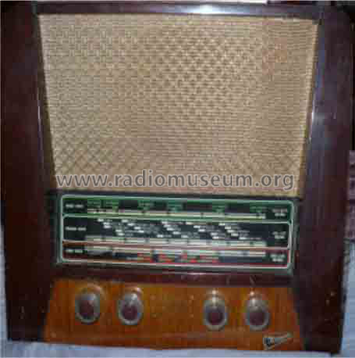

Severe Woodworm!

Before Restoration.


Click on the schematic thumbnail to request the schematic as a free document.
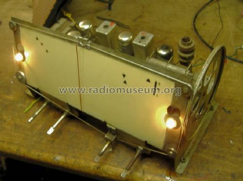
- Number of Tubes
- 5
- Main principle
- Superheterodyne (common); ZF/IF 470 kHz; 2 AF stage(s)
- Tuned circuits
- 6 AM circuit(s)
- Wave bands
- Broadcast, Long Wave and Short Wave.
- Power type and voltage
- Alternating Current supply (AC) / 195-255 Volt
- Loudspeaker
- Permanent Magnet Dynamic (PDyn) Loudspeaker (moving coil) / Ø 25 cm = 9.8 inch
- Material
- Wooden case
- from Radiomuseum.org
- Model: T38A - Marconi Co. Marconiphone,
- Shape
- Tablemodel, with any shape - general.
- Dimensions (WHD)
- 420 x 325 x 220 mm / 16.5 x 12.8 x 8.7 inch
- Notes
-
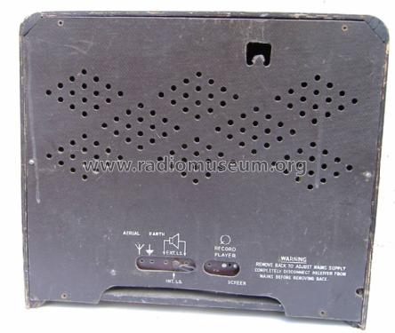
Model plate is on base.
The Output Transformer has a tap to act as choke for HT for V1 to V3 and V4 g2/Screen grid.
The "earthy" pin of the P.U./Gram connector shorts out the Anode L.O. signal of the X148 Triode section to "disable" reception as the Wave band switch has no "Gram/PU." position. See the similar T26A and T29A (two preset stations and no choke tap on o/p but same loudspeaker, similar tuning scale, similar circuit on different chassis).
The rear plate of scale has the index position for pointer when tuning is fully meshed as well as two calibration points for each band. R&TVS doesn't list the frequencies, nor are the T29A alignment instructions suitable. The low frequency end of band marks are for L7, L9 and L10. In practice the trimmers (but not L.O. coils) for HF ends of bands can be aligned with the set in the Radio. 17MHz, 200m and 1000m scale positions are close to rear panel marks and can be used for the trimmer adjustments in the cabinet.
Trimmer Capacitor designations may be only the R&TVS schematics.
(check fully pointer aligns on right when fully meshed first)
T38A Frequency L.O. R.F. 17MHz (SW) TC3 TC6 1500kHz (200m MW) TC4 TC1 300kHz (1000m LW) TC5 TC2 Order from side wall is LW, MW, SW. The R.F. trimmers are near scale on top of chassis and L.O. trimmers are on the rear of chassis,
A large foil plate on one side wall of the cabinet functions as the internal aerial.
- Mentioned in
- -- Original-techn. papers.
- Author
- Model page created by Peter Hoddow. See "Data change" for further contributors.
- Other Models
-
Here you find 502 models, 335 with images and 317 with schematics for wireless sets etc. In French: TSF for Télégraphie sans fil.
All listed radios etc. from Marconi Co. (Marconiphone, Marconi's Wireless Telegraph Co. Ltd.), GB (not tubes - see also HMV His Master's Voice)