- Produttore / Marca
- Marconi Co. (Marconiphone, Marconi's Wireless Telegraph Co. Ltd.), GB (not tubes - see also HMV His Master's Voice)
- Anno
- 1954
- Categoria
- Radio (o sintonizzatore del dopoguerra WW2)
- Radiomuseum.org ID
- 105201
Clicca sulla miniatura dello schema per richiederlo come documento gratuito.
- Numero di tubi
- 5
- Principio generale
- Supereterodina (in generale); ZF/IF 470 kHz; 2 Stadi BF
- N. di circuiti accordati
- 6 Circuiti Mod. Amp. (AM)
- Gamme d'onda
- Onde medie (OM), lunghe (OL) e corte (OC).
- Tensioni di funzionamento
- Alimentazione a corrente alternata (CA) / 195-255 Volt
- Altoparlante
- AP magnetodinamico (magnete permanente e bobina mobile) / Ø 25 cm = 9.8 inch
- Materiali
- Mobile in legno
- Radiomuseum.org
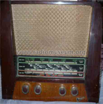
- Modello: T38A - Marconi Co. Marconiphone,
- Forma
- Soprammobile con qualsiasi forma (non saputo).
- Dimensioni (LxAxP)
- 420 x 325 x 220 mm / 16.5 x 12.8 x 8.7 inch
- Annotazioni
-
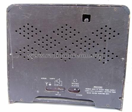
Model plate is on base.
The Output Transformer has a tap to act as choke for HT for V1 to V3 and V4 g2/Screen grid.
The "earthy" pin of the P.U./Gram connector shorts out the Anode L.O. signal of the X148 Triode section to "disable" reception as the Wave band switch has no "Gram/PU." position. See the similar T26A and T29A (two preset stations and no choke tap on o/p but same loudspeaker, similar tuning scale, similar circuit on different chassis).
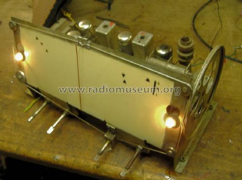
The rear plate of scale has the index position for pointer when tuning is fully meshed as well as two calibration points for each band. R&TVS doesn't list the frequencies, nor are the T29A alignment instructions suitable. The low frequency end of band marks are for L7, L9 and L10. In practice the trimmers (but not L.O. coils) for HF ends of bands can be aligned with the set in the Radio. 17MHz, 200m and 1000m scale positions are close to rear panel marks and can be used for the trimmer adjustments in the cabinet.
Trimmer Capacitor designations may be only the R&TVS schematics.
(check fully pointer aligns on right when fully meshed first)
T38A Frequency L.O. R.F. 17MHz (SW) TC3 TC6 1500kHz (200m MW) TC4 TC1 300kHz (1000m LW) TC5 TC2 Order from side wall is LW, MW, SW. The R.F. trimmers are near scale on top of chassis and L.O. trimmers are on the rear of chassis,
A large foil plate on one side wall of the cabinet functions as the internal aerial.
- Bibliografia
- -- Original-techn. papers.
- Autore
- Modello inviato da Peter Hoddow. Utilizzare "Proponi modifica" per inviare ulteriori dati.
- Altri modelli
-
In questo link sono elencati 503 modelli, di cui 339 con immagini e 321 con schemi.
Elenco delle radio e altri apparecchi della Marconi Co. (Marconiphone, Marconi's Wireless Telegraph Co. Ltd.), GB (not tubes - see also HMV His Master's Voice)


