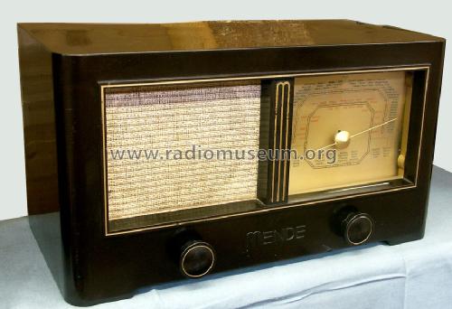
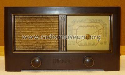
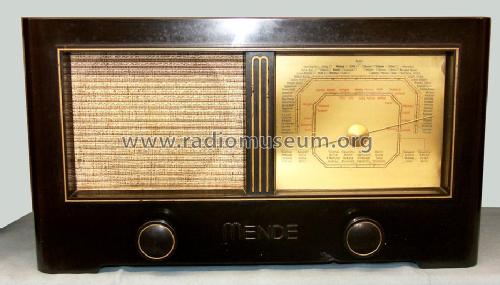
MS172-W (172W)
Mende - Radio H. Mende & Co. GmbH, Dresden
- País
- Alemania
- Fabricante / Marca
- Mende - Radio H. Mende & Co. GmbH, Dresden
- Año
- 1941–1943
- Categoría
- Radio - o Sintonizador pasado WW2
- Radiomuseum.org ID
- 3647
-
- Brand: System Günther


ebay 6600551067
ebay 6600551067

ebay 6600551067


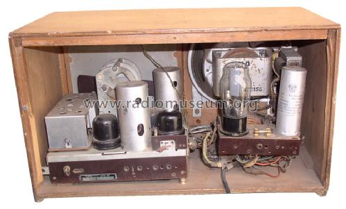


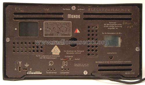


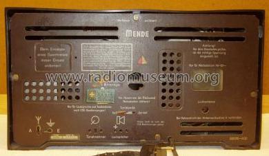
Mende 172W back view
Haga clic en la miniatura esquemática para solicitarlo como documento gratuito.
- Numero de valvulas
- 4
- Principio principal
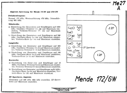
- Superheterodino en general; ZF/IF 468 kHz
- Número de circuitos sintonía
- 6 Circuíto(s) AM
- Gama de ondas
- OM, OL y OC
- Tensión de funcionamiento
- Red: Corriente alterna (CA, Inglés = AC) / 110-240 Volt
- Altavoz
- Altavoz electrodinámico (bobina de campo)
- Material
- Bakelita
- de Radiomuseum.org
- Modelo: MS172-W - Mende - Radio H. Mende & Co.
- Forma
- Sobremesa de cualquier forma, detalles no conocidos.
- Ancho, altura, profundidad
- 420 x 235 x 210 mm / 16.5 x 9.3 x 8.3 inch
- Anotaciones
- Das Typschild des Empfängers zeigt MS172-W, dagegen führen die Service-Unterlagen die Typbezeichnung 172W.
Es handelt sich dabei um dasselbe Modell.
- Peso neto
- 9 kg / 19 lb 13.2 oz (19.824 lb)
- Procedencia de los datos
- Radiokatalog Band 1, Ernst Erb
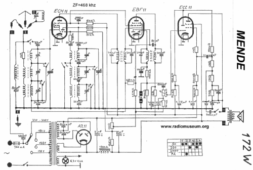
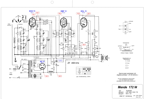
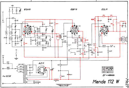
- Referencia esquema
- Lange+Schenk+FS-Röhrenbestückung
- Mencionado en
- Funkgeschichte der GFGF (9284)
- Referencia ilustración
- Das Modell ist im «Radiokatalog» (Erb) abgebildet.
- Otros modelos
-
Donde encontrará 317 modelos, 284 con imágenes y 207 con esquemas.
Ir al listado general de Mende - Radio H. Mende & Co. GmbH, Dresden
Colecciones
El modelo es parte de las colecciones de los siguientes miembros.
Contribuciones en el Foro acerca de este modelo: Mende - Radio H.: MS172-W
Hilos: 2 | Mensajes: 7
Hallo Sammlerfreunde,
ich möchte mal wieder auf einen Fehler im Schaltplan hinweisen. Die Gegenkopplung von der ECL 11 rechts oben im ersten Schaltplan ist falsch gezeichnet. Das betrifft leider auch den Plan im Empfänger Vade-Mecum S.995 . Die beiden anderen Schaltpläne im RM kann ich nicht beurteilen, da ich sie mir aus bekannten Gründen nicht heruntergeladen habe und die Quelle nicht kenne.
Herzliche Grüße
M. Böhme
Mario Böhme, 04.Dec.14
Greetings!
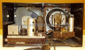
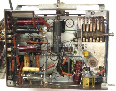
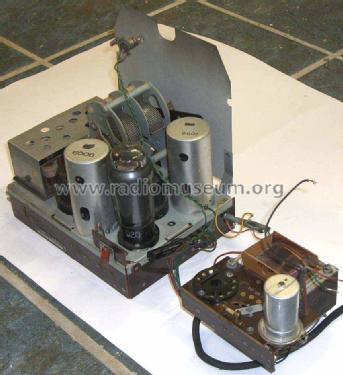
I have one of these Mende 172W radios in which the speaker has been disconnected. I am having trouble understanding the connections to the field coil.
There are 4 connections and four wires going to the field.
In the picture below, I have numbered the connections.
Between 1 and 2, I measure. 3.4 K ohms. Also 3.4 K ohms between points 3 and 4. So it seems that there are 2 windings in the field. There is no connection between the 2 fields.
Between points 5 and 6 measures 600 ohms, so that is the primary of the speaker transformer. No problem there.
Can anyone explain to me why there are these 2 fields and how they should be connected up? The schematic diagram gives a measurement of 1500 Ohms for the field.
Is it that the fields should be connected in parallel?
Sorry, but my German is not quite good enough to explain this problem.
Thanks
Peter
Anexos
- Mende speaker (118 KB)
- Mende speaker 1 (119 KB)
Peter Hughes, 23.May.14