15-watt Cathamplifier
Mingay's Wireless Manufacturing Ltd.; Sydney
- País
- Australia
- Fabricante / Marca
- Mingay's Wireless Manufacturing Ltd.; Sydney
- Año
- 1950 ?
- Categoría
- Amplificador de audio o mezclador
- Radiomuseum.org ID
- 339938
Haga clic en la miniatura esquemática para solicitarlo como documento gratuito.
- Numero de valvulas
- 4
- Principio principal
- Amplificador de Audio
- Gama de ondas
- - no hay
- Tensión de funcionamiento
- Red: Corriente alterna (CA, Inglés = AC) / 240 Volt
- Altavoz
- - Este modelo usa altavoz exterior (1 o más).
- de Radiomuseum.org
- Modelo: 15-watt Cathamplifier - Mingay's Wireless
- Anotaciones
-
15-watt Cathamplifier
The Cathamplifier was developed by Charles A. Parry in 1949-50.
It was a self-split, cathode‐driven push‐pull technique with a relatively low parts count.
It required special transformers which were manufactured by Ferguson Transformers and Nova Electrical & Engineering Co.It could be used for output stages for radio receivers and amplifiers.
Four models with outputs from 4.5-watts to 40 watts were described in Mingays, The Cathamplifier Handbook of 1951.
Full design details were published in the Australasian Radio Weekly, June 1950, and the Proceedings of the I.R.E., April 1950, page 460.
- Mencionado en
- -- Original-techn. papers. (Mingays, The Cathamplifier Handbook of 1951, Page 9.)
- Autor
- Modelo creado por Gary Cowans. Ver en "Modificar Ficha" los participantes posteriores.
- Otros modelos
-
Donde encontrará 9 modelos, 8 con imágenes y 2 con esquemas.
Ir al listado general de Mingay's Wireless Manufacturing Ltd.; Sydney
Contribuciones en el Foro acerca de este modelo: Mingay's Wireless: 15-watt Cathamplifier
Hilos: 1 | Mensajes: 1
Extracted from Australasian Radio World, June 1950. Pages 7–12.The
The Parry Cathamplifier
By C. A. PARRY, A.M.I.R.E. Consulting Engineer Sydney N.S.W.
The original Parry Cathamplifier was first featured in the “Radio and Electrical Weekly and has aroused widespread interest.
This circuit represents a substantial improvement in amplifier technique and “Australasian Radio World” is happy to be able to present this feature article.
By special arrangement with the designer, ”Radio World” has obtained the design procedure and data relating to the prototype 15-watt amplifier.
Of particular interest to experimenters and technicians, the article shows how an amplifier of required performance may be designed on paper and constructed to substantially verify expectations.
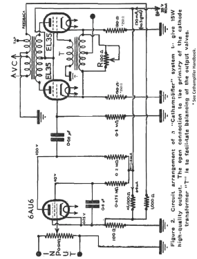
This unique development permits an amplifier to be constructed with only a few components, yet will give less than 0.5% distortion at 15 watts output for only a fraction of a volt input.
The author has recently developed a circuit that enables push-pull operation to be achieved by much simpler means than hitherto. This circuit has been used as the basis for an extremely compact amplifier.
This article shows how the design of a practical amplifier may be carried out. Of particular interest is the manner in which a straightforward engineering procedure is used to obtain predictable performance, eliminating the more usual time-consuming “cut and try” methods.
The extreme simplicity, low cost, and excellent performance of this remarkable amplifier should commend it to all technicians.
THE BASIC CATHAMPLIFIER CIRCUIT
The basic circuit used to obtain push-pull operation is shown in Fig. 1a, Figs. 1b and 1c show variations of this.
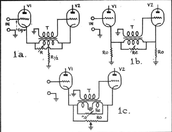
Fig. 1b does not require a centre-tapped transformer, and Fig. 1c permits both AC and DC balancing of the output valves.
A transformer “T” is placed in the cathode circuit of the output valves as shown. The circulating AC current of the valves produces a voltage across the primary, the magnitude being adjusted by “R”. By means of the transformer, a voltage in the correct phase can be fed into the grid of valve 2, so obtaining push-pull operation.
The circuit has a number of advantages as far as push-pull operation is concerned. Very few parts are required. The transformer “T” is simple in design and, because it is in a low impedance circuit, can be small physically.
The input circuit is unbalanced and has high impedance. Thus, the push-pull stage can be fed by a high-gain pentode and a high-gain amplifier of compact construction is possible.
If feedback from the output stages is contemplated, the influence of the cathode transformer is relatively small, simplifying the design. Also, since adequate sensitivity with only one extra stage becomes feasible, the feedback voltage need only be applied over two stages, ensuring much greater inherent stability.
The balance adjustment “R” is only small in value, hence a stable wire-wound resistor may be used, and great stability of adjustment is assured.
When balanced it may be shown that, Where R = 1/G (T-½).
Where G = the change in cathode current for a given change in grid voltage.
T = the ratio secondary to the whole primary of the cathode transformer.
Other formulae may be developed for distortion, sensitivity, and so on.
Balance is easily adjusted, either by observing equality of grid voltages or by obtaining minimum AC voltage from the centre tap of the primary of the cathode transformer to earth.
The choice of the transformation ratio “T” is an arbitrary one, but should never be less than 1. The value selected by the author for the initial design was 3.3.
INITIAL CONSIDERATIONS
If an advantage is to be taken of this circuit, to develop a compact and simple amplifier, at what point should we start?
it seems that for a first design, a 15-watt unit is reasonable.
If this output can be obtained for less than 0.5-volt input, then the amplifier might be regarded as a basic amplifier unit. The ideal requirement of such a basic unit can be readily stated.
(a) Size small, simple, compact.
(b) Response from 30 to 15,000 cycles plus or minus 1 decibel.
(c) Adequate speaker damping.
(d) Low harmonic distortion (less than 2.5 %).
(e) For 15 watts output, less than 0.5-volt input.
(f) Good inherent stability.
(g) Low noise.
There may be some who will maintain that bass and treble boost should be included by adaptation of the feedback circuit. Such arrangements complicate the design, quite often reduce the speaker damping or introduce instability, and cause more trouble than they cure. They represent bad engineering methods. The basic amplifier should be regarded as an integral part of the speaker system.
The whole unit amplifier plus speaker may well be regarded as the electro-acoustic transducer. The characteristics of the amplifier must help to overcome and supplement the shortcomings of the speaker system.
If correction units are required, as undoubtedly, they will be, then they should be placed between the input circuit and the basic amplifier.
Attention to this important principle would eliminate a great deal of the controversial discussion of amplifier “quality.”
VALVE SELECTION
In order to take full advantage of the possibilities of the circuit, careful valve selection is necessary. If sufficiently sensitive valves can be used, feedback may be applied over, perhaps, only two stages, yet the resulting sensitivity may still be adequate.
A combination of EL35’s for the output, driven by a resistance-coupled 6AU6G stage is an interesting suggestion, and after some preliminary calculations, was used for a trial design.
Using manufacturer’s curves, it is possible to tabulate expected operating conditions. Thus, we obtain Table No. 1.
TABLE No. 1
| Output Valves | |
| Volts anode to cathode (max. sig.), (less drop in transformer) | 295 V |
| Volts screen to cathode (max. sig.) | 295V |
| Bias (no sig.) | 17.5 V |
| Valve current (x2) (no sig.) | 130 mA |
| Valve current (x2) (max. sig.) | 150 mA |
| Bias resistor (per valve) | 135 Ω |
| Bias at max. sig. | 20 V |
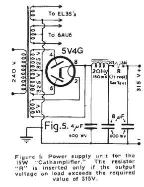
| HT supply at max. sig | 315 V |
| Transconductance (low sig.) | 8.5 mA/V |
| Transconductance (med sig.) | 6 mA/V |
| Transconductance (large sig.) | 5.4 mA/V |
| Amplification factor | 191 |
| AC plate resistance (per valve) | 22,000 Ω |
| Recommended load (per valve) | 2250 Ω |
| Watts output (Due to slightly higher supply voltage this will be somewhat greater than 20 W) | 20 W |
| Probable distortion for 20 watts (primary) | 4% |
| Output for transformer efficiency of 75% | 15 W |
| Grid drive for full output | 18 V peak |
| Driver Valve | |
| Anode load resistance | 200,000 Ω |
| Anode current | 1 mA |
| Cathode current | 1.4 mA |
| Bias | 0.75 V |
| Anode volts | 100 V |
| Screen volts | 40 V |
| Transconductance | 2.5 mA/V |
| Bias resistor | 535 Ω |
| Following grid resistor | 500,000 Ω |
| Effective AC plate load | 143,000 Ω |
| Screen dropping resistor | 675,000 Ω |
The figures obtained from this table may now be used to proceed with the design of the feedback circuit and predict the overall performance.
DESIGN PROCEDURE
The circuit in Fig. 1b will be used for the output circuit. Taking the constants already shown, the value of the balancing resistor “R” calculated at a low signal level is 67 Ω. Although the value required for balance varies with different signal levels slightly, a 100 Ω potentiometer will suffice. We get an anticipated distortion (without overall feedback) of about 6.8%. The full output should be obtained with a grid-to-earth AC voltage (output valves) of only 15 V RMS.
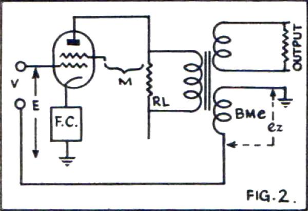
Of the several feedback circuits which may be used, the most suitable for an amplifier of this type is to couple from the output transformer via a low impedance winding back to the cathode of the driver stage. The basic equivalent of this (referred to the output valves) is indicated in Fig. 2.
There are generally two points at which the design may start. Either a given sensitivity may be considered, or a given effective valve impedance. This latter will be the basis for the design herein.
The magnitude of the valve impedance to be obtained is quite arbitrary. Good damping on the speaker (low output impedance and damping factor) means low sensitivity. Too great damping, on the other hand, serves no useful purpose.
A value of damping factor between 0.1 and 0.4 seems generally satisfactory. A figure of one-seventh is usually used by the author in initial designs. Allowing for some effect of the output transformer, and possible discrepancies between calculated and obtained results, the final figure so achieved, is usually quite OK. This value was used in the design of the prototype amplifier.
Thus from the valve constants, we are able to obtain a value for the required feedback factor B = 0.425, referred to one output valve. When considering the transformation ratio referred to the whole primary, this figure is of course halved. In Fig. 2 it is possible to show that
V = E (1 + BM /F).
Where M = nominal amplification, F = gain reduction factor.
This means that the feedback will reduce the gain by the value (1 + BM / F) and thus the influence on sensitivity of the feedback constants may be determined.
Also, the amount by which distortion is reduced may be calculated.
Measurement of the ratio, gain without feedback/gain with feedback, is a quite powerful method of determining that the amplifier is operating in accordance with expectations, and using the data mentioned, a value for this amplifier of 14 to 15 dB was calculated. This is a comparatively low figure for a high-quality amplifier.
However, as the estimated distortion with this feedback was quite low, no change to the constants so far determined was made. With a low value for the ratio referred to; the feedback loop is relatively easy to design, and this reduces the possibility of inherent instability, a factor which often is hard to eliminate and ruins an otherwise perfect piece of equipment.
Once the essential behavior of the equivalent circuit has been investigated the overall feedback circuit initially suggested may be examined. The arrangement of this is shown in Fig. 3.
The choice of values for R1 and R2 is more or less arbitrary, but attention to small details permits considerable overall simplification. It will be readily appreciated that, if the gainof valve 1 is large, a large transformation ratio for the feedback winding could result. For instance, in this particular case, it would not be unreal to calculate less than one turn for the feedback winding. A suitable ratio of R1/R2 therefore considerably simplifies the output transformer design.
Too large a value for R1 however would reduce the effective amplification of valve 1.
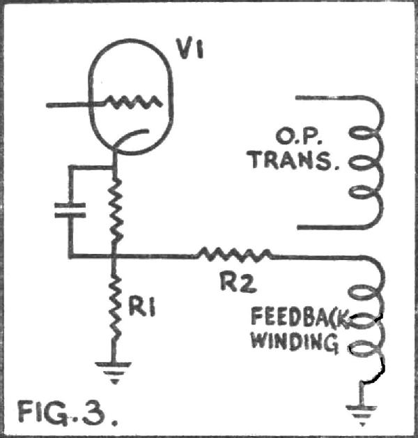
If R1 is carefully chosen the possibility of bias being obtained by additional bleed current is opened. The idealised arrangement is shown on the full circuit of Fig. 4. With the constants shown (the process by means of which the actual values were originally determined is beyond the scope of the present article) the effective cathode impedance of valve 1 is only 90 ohms. This value results in a calculated gain of 290 for the 6AU6G stage.
Once this figure is obtained the transformation ratio for the feedback winding on the output transformer may be obtained.
Bb = B.Ra/Ga.
Where Bb= effective feedback factor expressed practically by the ratio, feedback turns/whole primary turns and referred to the output transformer.
B = feedback factor obtained from the equivalent circuit of Fig. 2.
Ra = ratio (R 1 + R2)/R1 in Fig. 3.
Ga = gain of valve 1.
Using the constants determined so far Bb. = 0.008.
At full output the gain reduction by means of the overall feedback works out to a value of 5.4, and this enables the sensitivity to be obtained. The input to the grid of the driven output valve must be 15 volts, the gain reduction is 5.4, and the gain of valve 1 is 290, thus the input required is 0.28 volts. This is quite good sensitivity and means that the constants need not be changed until at least an experimental verification is obtained. If the experimental figure is reasonably close to this there would be no need to go to the trouble of further changes'
PERFORMANCE
It will be realised that all the component values for the full circuit of Fig. 4 have now been determined, and the anticipated performance figures of the complete amplifier have been calculated. The details in table 2 give measured data.
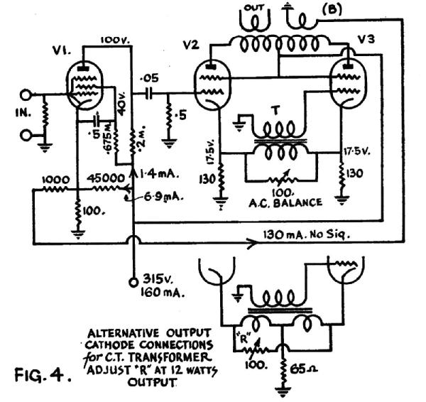
TABLE No. 2
(High tension supply 310 volts).
| Item | Estimated | Measured |
|---|---|---|
| 6AU6G | ||
| Plate volts | 100 | 115 |
| Screen volts | 40 | 40 |
| Bias volts | 0.75 | 0.85+ |
| Gain | 290 | 296 |
| EL35's | ||
| Bias no signal | 17.5 | 17.5 |
| Cathode current no signal | 130 | 134 |
| Output impedance 1kHz, 15 kΩ | 2.14 | 2.3 |
| Gain at max.signal | 1 | 1 |
| Ratio gain without FB/with FB | 14-15 dB | 14.5 dB |
| Input V for full output | 0.28 | 0.24 |
FREQUENCY RESPONSE
Fig. 5 shows the frequency response with and without feedback.
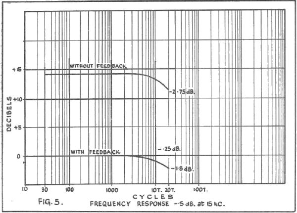 The absence of appreciable loss without feedback, at low frequencies, means that full output may be expected.
LINEARITY
Linearity is shown in Fig. 6.
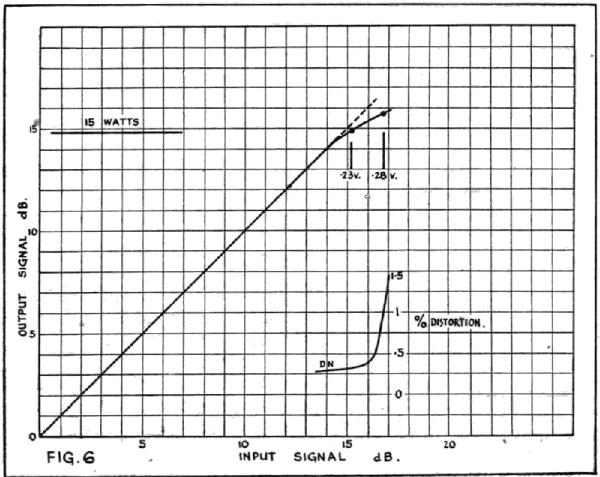
The gradual departure from linearity is a desirable feature. The amplifier is essentially linear to 15 watts. The departure from linearity above this is to be expected despite the use of an efficient output transformer.
MODIFICATION
Slight modification to the circuit might permit slightly greater output. It is interesting to note that a the point at which the output is beginning to have noticeable distortion, the output voltage is 0.28, the figure at which it was estimated full output should occur.
DISTORTION
On Fig. 6 is also plotted distortion at 500 cycles. At 15 watts the figure is excellent.
Again it is interesting to note that at 0.28 volts input the distortion is 1.4% . This is close to the design figure.
From the curves of Fig. 6, it would appear that the design figures are substantially correct, but that the output transform er is more efficient than that permitted in the initial design (so obtaining higher output in the load for the same power in the primary), but that, as expected, a slight degree of non-linearity near full output has occurred.
A measurement of distortion at 60 cycles was attempted, and although less than 1% was obtained a t 15 watts output, the distortion in the oscillator could not reliably be obtained, and so no definite value at this frequency can be quoted.
OUTPUT IMPEDANCE
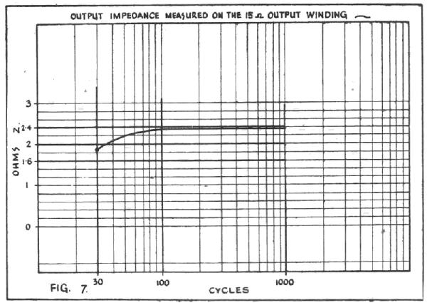
Fig. 7 shows the absolute value of output impedance over the low frequency portion of the spectrum. This is measured on the 15 Ω load winding.
As might be expected there is a drop at low frequency where the transform er inductance becomes effective.
STABILITY
A variation of plus or minus 35 volts on the HT supply varied the output at 1000 cycles by less than 0.1 dB. This degree of stability is of course to be expected.
The inherent stability of the circuit with and without load was checked and found to be quite satisfactory. No special precautions are necessary to avoid low frequency instability. The square wave response at 30 cycles is excellent.
ACKNOWLEDGEMENTS
I am very much indebted to the Ferguson Transformer Company who provided the transformers required for this amplifier, and also to Mr. R. Meadows of “Radio and Electrical Weekly,” who assisted in most of the measuring required on the prototype and who conducted extensive listening tests with the amplifier.
Gary Cowans, 28.Aug.22