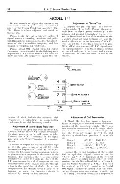
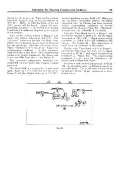
144X (144, 144E) Early
Philco, Philadelphia Stg. Batt. Co.; USA
- Pays
- Etats-Unis
- Fabricant / Marque
- Philco, Philadelphia Stg. Batt. Co.; USA
- Année
- 1934
- Catégorie
- Radio - ou tuner d'après la guerre 1939-45
- Radiomuseum.org ID
- 140609
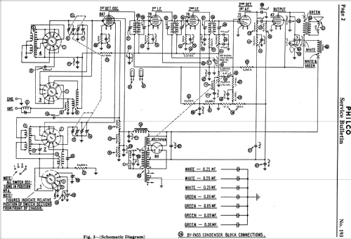
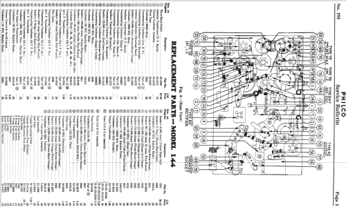
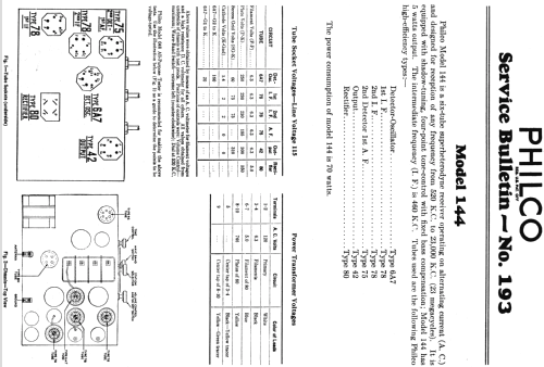
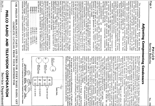
Cliquez sur la vignette du schéma pour le demander en tant que document gratuit.
- No. de tubes
- 6
- Principe général
- Super hétérodyne (en général); FI/IF 260 kHz
- Gammes d'ondes
- PO et plus que 2 x OC
- Tension / type courant
- Alimentation Courant Alternatif (CA) / 115 Volt
- Haut-parleur
- HP dynamique à électro-aimant (électrodynamique)
- Puissance de sortie
- 5 W (qualité inconnue)
- Matière
- Boitier en bois
- De Radiomuseum.org
- Modèle: 144X [Early] - Philco, Philadelphia Stg. Batt
- Forme
- Console de forme générique
- Remarques
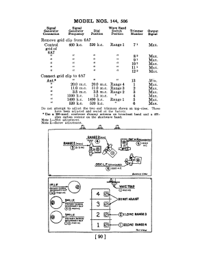
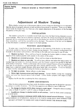
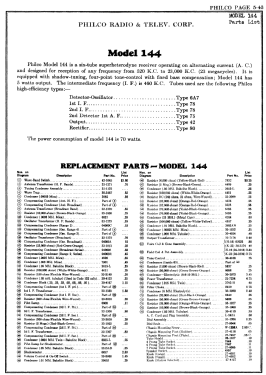
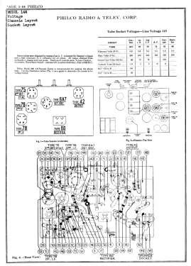
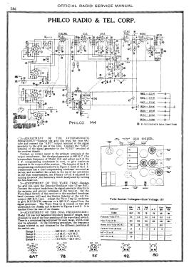
- The Philco 144 series was a follow-on to the model 44 series of all-wave radios. The model 144 chassis has six tubes and covers BC to 23 MHz in four bands. It has a shadow meter (tuning aid) and a four position tone control. The standard 144 chassis was designed for 115 VAC 50-60 Hz, and the 144E export version (code 125) of the chassis was designed for 230 VAC 50-60 Hz.
There are six individual models in the series with different cabinet styles. The early version (1934) of the 144B table radio is a cathedral with scalloped top. The late version (1935) of 144B is a shouldered tombstone having a lyre-shaped speaker opening with three vertical bars through the center of the opening.
Model 144H (1934-35) is a highboy with six legs and a Y-shaped speaker opening with vertical bars. Model 144D (1934) is a similar highboy design with doors.
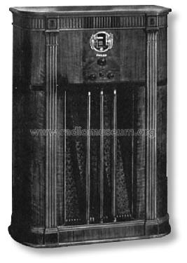
The early version (1934) of the 144X floor-type console has a classical design, with three round pillars in front of the inclined sounding board. The late version (1934-35) of 144X has a somewhat more modern design with three square fluted pillars in front of the speaker and an emblem at the top center of the cabinet.
- Source
- Philco Radio 1928-1942
- Source du schéma
- Rider's Perpetual, Volume 5 = ca. 1934 and before
- Littérature
- Pre-War Consoles
- Schémathèque (1)
- Philco Service Bulletin # 193; Philco Wiring Diagrams, Parts Lists, and Essential Serv. Data 1928-36
- Auteur
- Modèle crée par Thomas Albrecht. Voir les propositions de modification pour les contributeurs supplémentaires.
- D'autres Modèles
-
Vous pourrez trouver sous ce lien 4041 modèles d'appareils, 2217 avec des images et 3690 avec des schémas.
Tous les appareils de Philco, Philadelphia Stg. Batt. Co.; USA
