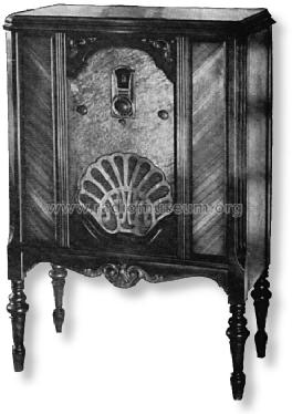
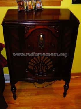
95 Lowboy
Philco, Philadelphia Stg. Batt. Co.; USA
- Land
- USA
- Hersteller / Marke
- Philco, Philadelphia Stg. Batt. Co.; USA
- Jahr
- 1929/1930
- Kategorie
- Rundfunkempfänger (Radio - oder Tuner nach WW2)
- Radiomuseum.org ID
- 51248


Klicken Sie auf den Schaltplanausschnitt, um diesen kostenlos als Dokument anzufordern.
- Anzahl Röhren
- 9
- Hauptprinzip
- Geradeaus allg. (mit oder ohne Rückk.); Schirmgitter 1926-1935
- Anzahl Kreise
- 4 Kreis(e) AM
- Wellenbereiche
- Mittelwelle, keine anderen.
- Betriebsart / Volt
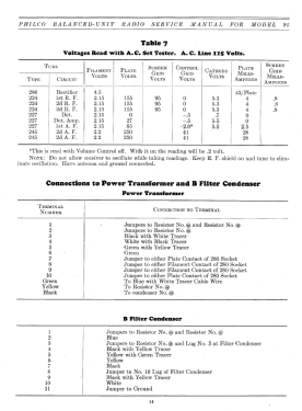
- Wechselstromspeisung / 115 Volt
- Lautsprecher
- Dynamischer LS, mit Erregerspule (elektrodynamisch)
- Material
- Gerät mit Holzgehäuse
- von Radiomuseum.org
- Modell: 95 Lowboy - Philco, Philadelphia Stg. Batt
- Form
- Standgerät auf niedrigen Beinen (Beine < 50 % der Gesamthöhe).
- Bemerkung
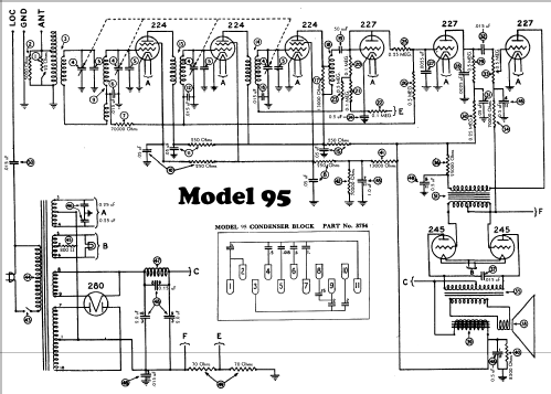
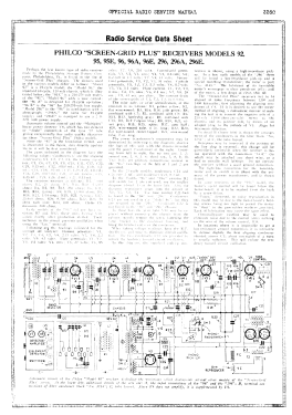
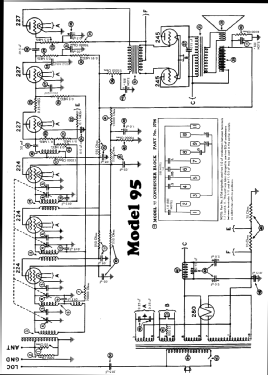
- Model 95 was a "Screen Grid Plus" model and was available in a table, lowboy, highboy, Tudor highboy, and deluxe highboy cabinet. One dial (primary tuning control knob). Lowboy cabinet is similar to models 76 and 87 lowboys.
- Originalpreis
- 149.00 $
- Datenherkunft extern
- Ernst Erb
- Datenherkunft
- Radio Collector`s Guide 1921-1932
- Schaltungsnachweis
- Rider's Perpetual, Volume 1 = 1931/1934 (for 1919-1931)
- Literaturnachweis
- Pre-War Consoles
- Literatur/Schema (1)
- Collector's Guide to Antique Radios (6th edition) (Philco 1928-36 Wiring Diagrams, Parts Lists, and Essential Service Data)
- Weitere Modelle
-
Hier finden Sie 4120 Modelle, davon 2227 mit Bildern und 3768 mit Schaltbildern.
Alle gelisteten Radios usw. von Philco, Philadelphia Stg. Batt. Co.; USA
Sammlungen
Das Modell 95 befindet sich in den Sammlungen folgender Mitglieder.
Forumsbeiträge zum Modell: Philco, Philadelphia: 95 Lowboy
Threads: 1 | Posts: 1
What a delightful set to work on. All the parts have no value written on them. Or some not listed anywhere Philco in-house part number. And of course, almost all the capacitors are potted in tar.
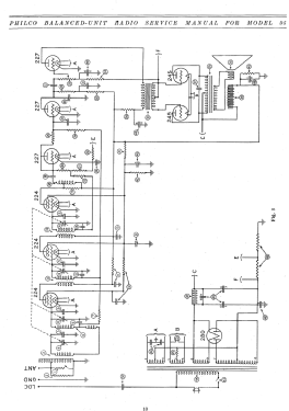
A thank you to the person who posted the schematic here. Unlike other online versions, this one is quite readable.
So, I sat down and generated a drawing of the bottom of the chassis so you know what all the unmarked parts are and what all the terminals are according to the numbers on the schematic.
http://www.radiomuseum.org/r/philco_lb_95.html
By the way, I have the original AutoCAD R12 .dxf file I made if anyone wants a copy of it.
Some notes on restoring this receiver:
There are three variations of cardboard tubes filled with tar mounted under the chassis. Six of them are simply a 0.015 uF capacitor. Four of them have a 0.05 uF capacitor and a 250 Ohm resistor. The last one has a 0.05 uF capacitor and uses the spare lug as a tie point for other wiring. All three are easy to unstuff. Using a curved shield on a heat gun, heat the part until the tar starts to weep at the ends. Push the tar out of the cardboard tube and clean up any excess tar with a dull knife. Mount the new component(s) in the cardboard tube, and stuff the center of the tube with tissue paper to act as a dam of sorts, then refill with the goo of your choice. I use hot melt glue, but I suspect some of you might want to go all the way and reclaim/reuse the original tar.
Mounted to the rear side of the chassis are two tin boxes. One has a single 0.05 uF capacitor, and the other has a pair of 0.025 uF capacitors. Both are almost painless to rebuild. Just unfold the tabs on the lead end, and push the innards out with a thin screwdriver.
Of course, now you have the true horror story to rebuild. The potted box with eight capacitors inside. The real problem with this is simply the crowded terminal strip on the bottom, three unmarked power resistors and the wiring loom attached to it.
TAKE LOTS OF NOTES when you untangle something like this. The wires are fragile and won't tolerate too many "Oh, it goes here instead".
I'll come back to this in a day or two after I've gotten that apart and rebuilt with any special comments or hazards to deal with. And of course, I'll be posting some pictures of what I did over the next week as well.
Also, almost all of the composition resistors have drifted off in value and will need to be replaced. I use epoxy formed with silicon molds to encase new resistors so that they look original. I figured, I might as well considering I went through the effort to restuff all the capacitors.
Jeff
Jeffrey Angus, 16.Feb.07