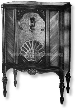
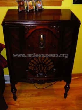
95 Lowboy
Philco, Philadelphia Stg. Batt. Co.; USA
- Pays
- Etats-Unis
- Fabricant / Marque
- Philco, Philadelphia Stg. Batt. Co.; USA
- Année
- 1929/1930
- Catégorie
- Radio - ou tuner d'après la guerre 1939-45
- Radiomuseum.org ID
- 51248


Cliquez sur la vignette du schéma pour le demander en tant que document gratuit.
- No. de tubes
- 9
- Principe général
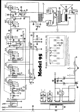
- Récepteur TRF en général (avec ou sans réaction inconnu); Tube à grille écran 1926-1935.
- Circuits accordés
- 4 Circuits MA (AM)
- Gammes d'ondes
- PO uniquement
- Tension / type courant
- Alimentation Courant Alternatif (CA) / 115 Volt
- Haut-parleur
- HP dynamique à électro-aimant (électrodynamique)
- Matière
- Boitier en bois
- De Radiomuseum.org
- Modèle: 95 Lowboy - Philco, Philadelphia Stg. Batt
- Forme
- Console avec pieds bas < 50% de la hauteur
- Remarques
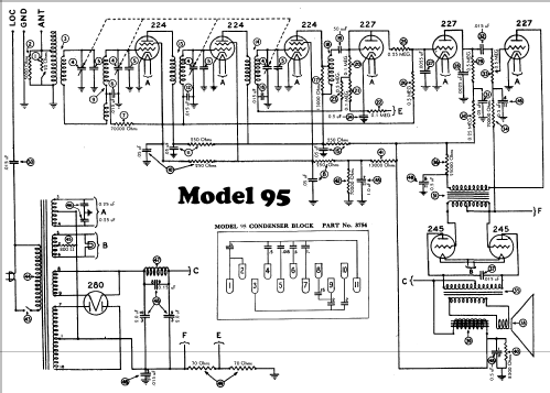
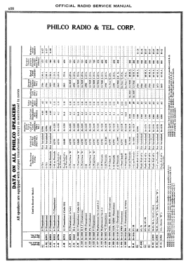
- Model 95 was a "Screen Grid Plus" model and was available in a table, lowboy, highboy, Tudor highboy, and deluxe highboy cabinet. One dial (primary tuning control knob). Lowboy cabinet is similar to models 76 and 87 lowboys.
- Prix de mise sur le marché
- 149.00 $
- Source extérieure
- Ernst Erb
- Source du schéma
- Rider's Perpetual, Volume 1 = 1931/1934 (for 1919-1931)
- Littérature
- Pre-War Consoles
- Schémathèque (1)
- Collector's Guide to Antique Radios (6th edition) (Philco 1928-36 Wiring Diagrams, Parts Lists, and Essential Service Data)
- D'autres Modèles
-
Vous pourrez trouver sous ce lien 4120 modèles d'appareils, 2227 avec des images et 3768 avec des schémas.
Tous les appareils de Philco, Philadelphia Stg. Batt. Co.; USA
Contributions du forum pour ce modèle: Philco, Philadelphia: 95 Lowboy
Discussions: 1 | Publications: 1
What a delightful set to work on. All the parts have no value written on them. Or some not listed anywhere Philco in-house part number. And of course, almost all the capacitors are potted in tar.
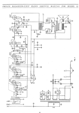
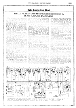
A thank you to the person who posted the schematic here. Unlike other online versions, this one is quite readable.
So, I sat down and generated a drawing of the bottom of the chassis so you know what all the unmarked parts are and what all the terminals are according to the numbers on the schematic.
http://www.radiomuseum.org/r/philco_lb_95.html
By the way, I have the original AutoCAD R12 .dxf file I made if anyone wants a copy of it.
Some notes on restoring this receiver:
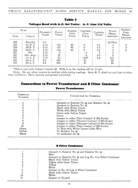
There are three variations of cardboard tubes filled with tar mounted under the chassis. Six of them are simply a 0.015 uF capacitor. Four of them have a 0.05 uF capacitor and a 250 Ohm resistor. The last one has a 0.05 uF capacitor and uses the spare lug as a tie point for other wiring. All three are easy to unstuff. Using a curved shield on a heat gun, heat the part until the tar starts to weep at the ends. Push the tar out of the cardboard tube and clean up any excess tar with a dull knife. Mount the new component(s) in the cardboard tube, and stuff the center of the tube with tissue paper to act as a dam of sorts, then refill with the goo of your choice. I use hot melt glue, but I suspect some of you might want to go all the way and reclaim/reuse the original tar.
Mounted to the rear side of the chassis are two tin boxes. One has a single 0.05 uF capacitor, and the other has a pair of 0.025 uF capacitors. Both are almost painless to rebuild. Just unfold the tabs on the lead end, and push the innards out with a thin screwdriver.
Of course, now you have the true horror story to rebuild. The potted box with eight capacitors inside. The real problem with this is simply the crowded terminal strip on the bottom, three unmarked power resistors and the wiring loom attached to it.
TAKE LOTS OF NOTES when you untangle something like this. The wires are fragile and won't tolerate too many "Oh, it goes here instead".
I'll come back to this in a day or two after I've gotten that apart and rebuilt with any special comments or hazards to deal with. And of course, I'll be posting some pictures of what I did over the next week as well.
Also, almost all of the composition resistors have drifted off in value and will need to be replaced. I use epoxy formed with silicon molds to encase new resistors so that they look original. I figured, I might as well considering I went through the effort to restuff all the capacitors.
Jeff
A thank you to the person who posted the schematic here. Unlike other online versions, this one is quite readable.
So, I sat down and generated a drawing of the bottom of the chassis so you know what all the unmarked parts are and what all the terminals are according to the numbers on the schematic.
http://www.radiomuseum.org/r/philco_lb_95.html
By the way, I have the original AutoCAD R12 .dxf file I made if anyone wants a copy of it.
Some notes on restoring this receiver:
There are three variations of cardboard tubes filled with tar mounted under the chassis. Six of them are simply a 0.015 uF capacitor. Four of them have a 0.05 uF capacitor and a 250 Ohm resistor. The last one has a 0.05 uF capacitor and uses the spare lug as a tie point for other wiring. All three are easy to unstuff. Using a curved shield on a heat gun, heat the part until the tar starts to weep at the ends. Push the tar out of the cardboard tube and clean up any excess tar with a dull knife. Mount the new component(s) in the cardboard tube, and stuff the center of the tube with tissue paper to act as a dam of sorts, then refill with the goo of your choice. I use hot melt glue, but I suspect some of you might want to go all the way and reclaim/reuse the original tar.
Mounted to the rear side of the chassis are two tin boxes. One has a single 0.05 uF capacitor, and the other has a pair of 0.025 uF capacitors. Both are almost painless to rebuild. Just unfold the tabs on the lead end, and push the innards out with a thin screwdriver.
Of course, now you have the true horror story to rebuild. The potted box with eight capacitors inside. The real problem with this is simply the crowded terminal strip on the bottom, three unmarked power resistors and the wiring loom attached to it.
TAKE LOTS OF NOTES when you untangle something like this. The wires are fragile and won't tolerate too many "Oh, it goes here instead".
I'll come back to this in a day or two after I've gotten that apart and rebuilt with any special comments or hazards to deal with. And of course, I'll be posting some pictures of what I did over the next week as well.
Also, almost all of the composition resistors have drifted off in value and will need to be replaced. I use epoxy formed with silicon molds to encase new resistors so that they look original. I figured, I might as well considering I went through the effort to restuff all the capacitors.
Jeff
Jeffrey Angus, 16.Feb.07