- Country
- Netherlands
- Manufacturer / Brand
- Philips; Eindhoven (tubes international!); Miniwatt
- Year
- 1940/1941
- Category
- Commercial Transmitter (TX not Transceiver)
- Radiomuseum.org ID
- 7212

Click on the schematic thumbnail to request the schematic as a free document.
- Number of Tubes
- 1
- Valves / Tubes
- EBC3
- Main principle
- Transmitter
- Tuned circuits
- 1 AM circuit(s)
- Wave bands
- Broadcast only (MW).
- Power type and voltage
- Powered by external power supply or a main unit. / 6,3 & DC 200 Volt
- Material
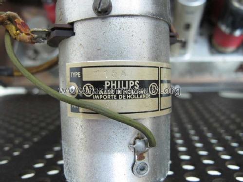
- Metal case, TUBES VISIBLE
- from Radiomuseum.org
- Model: 115A - Philips; Eindhoven tubes
- Shape
- Chassis only or for «building in»
- Dimensions (WHD)
- 46 x 46 x 200 mm / 1.8 x 1.8 x 7.9 inch
- Notes
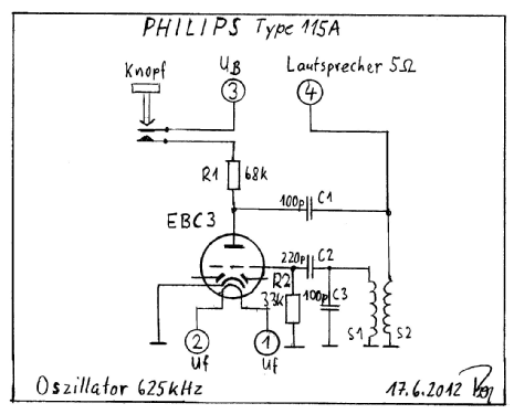
- Philips 115A ist ein AM-modulierbarer Oszillator für 625 kHz.
Optional zum Einbau in Radiogeräte, z.B. Philips 495X.
Über Anschluß 4: Ca. 50cm Drahtverbindung zum Lautsprecher-Anschluß 5 Ohm des Radiogerätes. Die Lautsprecher-Schwingspule ist somit frequenzbestimmend / parallel zu S2 und dient mit der Zuleitung gleichzeitig als Sendeantenne. Über die Bewegung der LS-Schwingspule erfolgt die AM-Modulation (Modulationsgrad ändert sich mit der Lautstärke). Siehe hierzu Schaltung.
Ermittelte Funktion: AM Sender mit geringer Reichweite zum Übertragen der Lautsprecher-Ausgabe auf MW 625 kHz.
- Source of data
- -- Schematic / Radiokatalog Band 1, Ernst Erb
- Circuit diagram reference
- Röhren in FS-Bestückungstabellen
- Other Models
-
Here you find 5271 models, 4415 with images and 3456 with schematics for wireless sets etc. In French: TSF for Télégraphie sans fil.
All listed radios etc. from Philips; Eindhoven (tubes international!); Miniwatt
Collections
The model is part of the collections of the following members.