- Country
- Netherlands
- Manufacturer / Brand
- Philips; Eindhoven (tubes international!); Miniwatt
- Year
- 1958/1959
- Category
- Broadcast Receiver - or past WW2 Tuner
- Radiomuseum.org ID
- 75954


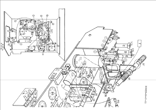
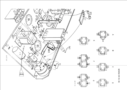


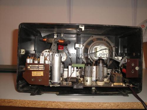


Innenansicht
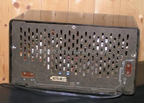
Rückwand
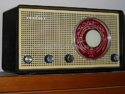


Skalenansichtt


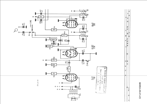
Click on the schematic thumbnail to request the schematic as a free document.
- Number of Tubes
- 5
- Main principle
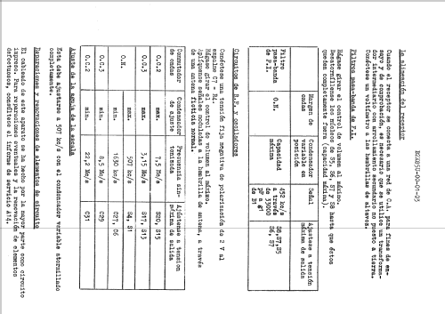
- Superheterodyne (common); ZF/IF 452 kHz
- Wave bands
- Broadcast plus 2 Short Wave bands.
- Power type and voltage
- AC/DC-set / 110, 127, 220 Volt
- Loudspeaker
- Permanent Magnet Dynamic (PDyn) Loudspeaker (moving coil)
- Material
- Bakelite case
- from Radiomuseum.org
- Model: B2X85U - Philips; Eindhoven tubes
- Shape
- Tablemodel, with any shape - general.
- Dimensions (WHD)
- 316 x 180 x 150 mm / 12.4 x 7.1 x 5.9 inch
- Notes
- Dial lamp: 8009D (6,3V/0,25A)
- Author
- Model page created by Petros Tsirvoulis. See "Data change" for further contributors.
- Other Models
-
Here you find 5271 models, 4415 with images and 3457 with schematics for wireless sets etc. In French: TSF for Télégraphie sans fil.
All listed radios etc. from Philips; Eindhoven (tubes international!); Miniwatt
Collections
The model is part of the collections of the following members.
Forum contributions about this model: Philips; Eindhoven: B2X85U
Threads: 1 | Posts: 4
I am restoring a radio Philips B2X85U (or B2K85U). I've got the schematics but I can not realize where to connect the 2 new capacitors in the place of the original can.
I mean, I have 2 capacitors with 4 leads and the PCB of the radio has 5 connection points on the original can.
I guess that the 2 negatives leads have a rail for both of them. Still, I have 4 connection for the other two positive leads.
There is a divider resistor that can solve one lead in two connections but the other positive lead will have to go to the other two connection points?
The pictures will show it.
What I need to know is where I can solder the 4 new leads?
Thanks,
Alvaro Georg
YouTube: Rádios Antigos & Cia Ltda
Brazil
Attachments
Alvaro Georg, 11.Jan.21