- País
- Holanda
- Fabricante / Marca
- Philips; Eindhoven (tubes international!); Miniwatt
- Año
- 1958/1959
- Categoría
- Radio - o Sintonizador pasado WW2
- Radiomuseum.org ID
- 75954


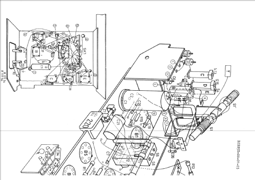
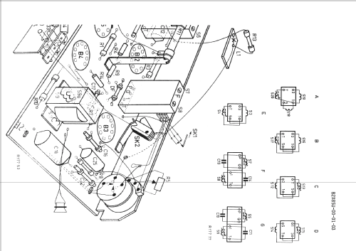


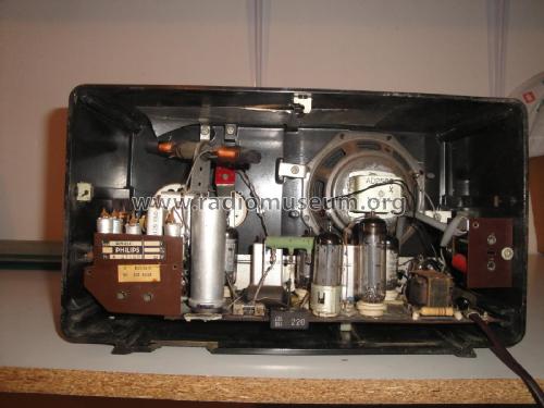


Innenansicht
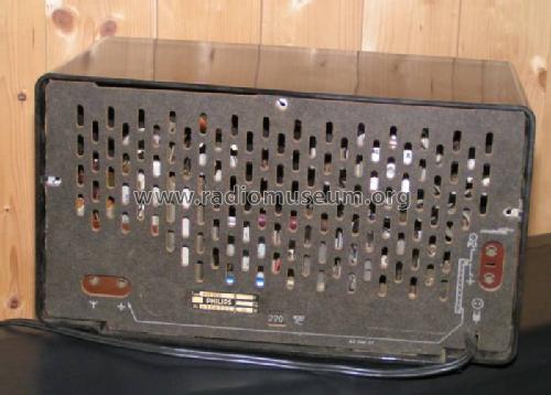
Rückwand
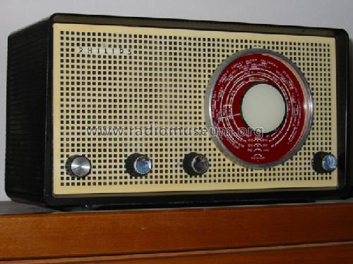


Skalenansichtt


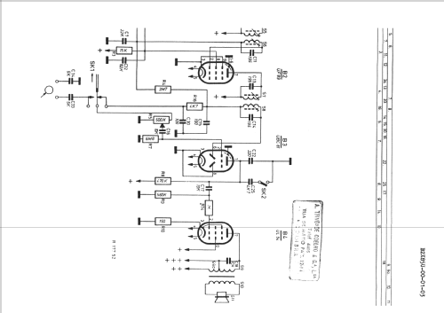
Haga clic en la miniatura esquemática para solicitarlo como documento gratuito.
- Numero de valvulas
- 5
- Principio principal
- Superheterodino en general; ZF/IF 452 kHz
- Gama de ondas
- OM y dos OC
- Tensión de funcionamiento
- Red: Aparato AC/DC. / 110, 127, 220 Volt
- Altavoz
- Altavoz dinámico (de imán permanente)
- Material
- Bakelita
- de Radiomuseum.org
- Modelo: B2X85U - Philips; Eindhoven tubes
- Forma
- Sobremesa de cualquier forma, detalles no conocidos.
- Ancho, altura, profundidad
- 316 x 180 x 150 mm / 12.4 x 7.1 x 5.9 inch
- Anotaciones
- Dial lamp: 8009D (6,3V/0,25A)
- Autor
- Modelo creado por Petros Tsirvoulis. Ver en "Modificar Ficha" los participantes posteriores.
- Otros modelos
-
Donde encontrará 5270 modelos, 4414 con imágenes y 3455 con esquemas.
Ir al listado general de Philips; Eindhoven (tubes international!); Miniwatt
Colecciones
El modelo es parte de las colecciones de los siguientes miembros.
Contribuciones en el Foro acerca de este modelo: Philips; Eindhoven: B2X85U
Hilos: 1 | Mensajes: 4
I am restoring a radio Philips B2X85U (or B2K85U). I've got the schematics but I can not realize where to connect the 2 new capacitors in the place of the original can.
I mean, I have 2 capacitors with 4 leads and the PCB of the radio has 5 connection points on the original can.
I guess that the 2 negatives leads have a rail for both of them. Still, I have 4 connection for the other two positive leads.
There is a divider resistor that can solve one lead in two connections but the other positive lead will have to go to the other two connection points?
The pictures will show it.
What I need to know is where I can solder the 4 new leads?
Thanks,
Alvaro Georg
YouTube: Rádios Antigos & Cia Ltda
Brazil
Anexos
Alvaro Georg, 11.Jan.21