- Paese
- Olanda
- Produttore / Marca
- Philips; Eindhoven (tubes international!); Miniwatt
- Anno
- 1958/1959
- Categoria
- Radio (o sintonizzatore del dopoguerra WW2)
- Radiomuseum.org ID
- 75954


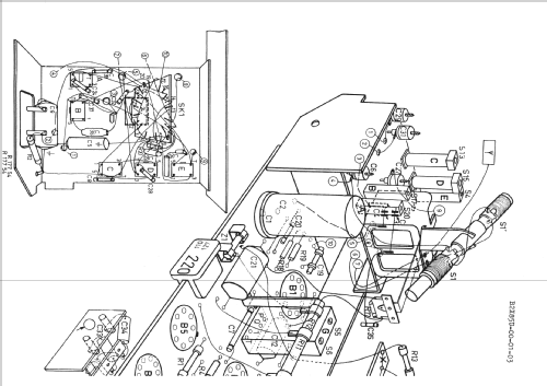
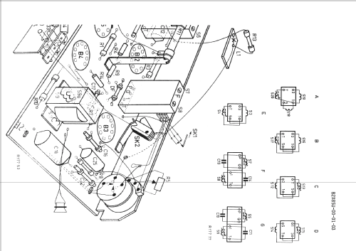


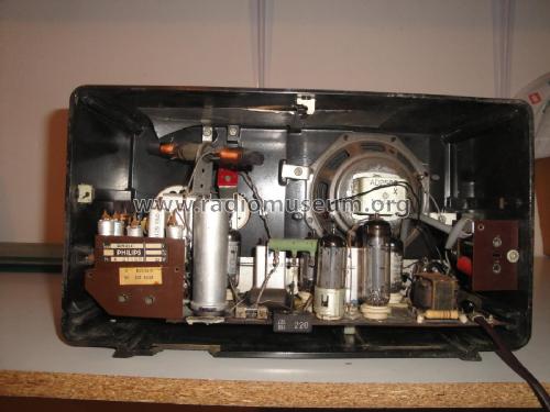


Innenansicht
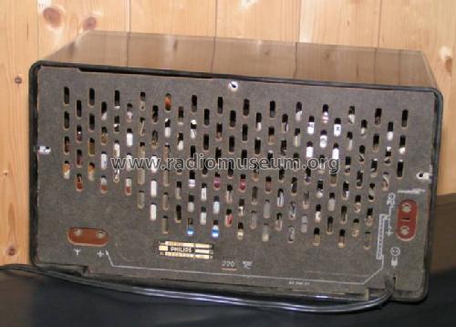
Rückwand
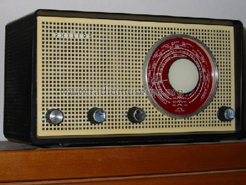


Skalenansichtt


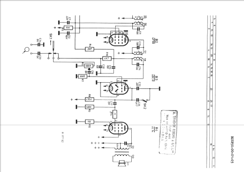
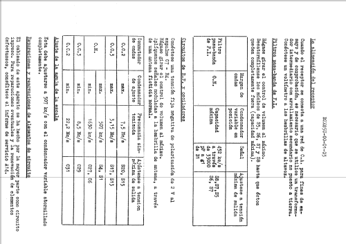
Clicca sulla miniatura dello schema per richiederlo come documento gratuito.
- Numero di tubi
- 5
- Principio generale
- Supereterodina (in generale); ZF/IF 452 kHz
- Gamme d'onda
- Onde medie (OM) e 2 gamme di onde corte (2 x OC).
- Tensioni di funzionamento
- Alimentazione universale (doppia: CC/CA) / 110, 127, 220 Volt
- Altoparlante
- AP magnetodinamico (magnete permanente e bobina mobile)
- Materiali
- Bachelite
- Radiomuseum.org
- Modello: B2X85U - Philips; Eindhoven tubes
- Forma
- Soprammobile con qualsiasi forma (non saputo).
- Dimensioni (LxAxP)
- 316 x 180 x 150 mm / 12.4 x 7.1 x 5.9 inch
- Annotazioni
- Dial lamp: 8009D (6,3V/0,25A)
- Autore
- Modello inviato da Petros Tsirvoulis. Utilizzare "Proponi modifica" per inviare ulteriori dati.
- Altri modelli
-
In questo link sono elencati 5243 modelli, di cui 4380 con immagini e 3446 con schemi.
Elenco delle radio e altri apparecchi della Philips; Eindhoven (tubes international!); Miniwatt
Collezioni
Il modello fa parte delle collezioni dei seguenti membri.
Discussioni nel forum su questo modello: Philips; Eindhoven: B2X85U
Argomenti: 1 | Articoli: 4
I am restoring a radio Philips B2X85U (or B2K85U). I've got the schematics but I can not realize where to connect the 2 new capacitors in the place of the original can.
I mean, I have 2 capacitors with 4 leads and the PCB of the radio has 5 connection points on the original can.
I guess that the 2 negatives leads have a rail for both of them. Still, I have 4 connection for the other two positive leads.
There is a divider resistor that can solve one lead in two connections but the other positive lead will have to go to the other two connection points?
The pictures will show it.
What I need to know is where I can solder the 4 new leads?
Thanks,
Alvaro Georg
YouTube: Rádios Antigos & Cia Ltda
Brazil
Allegati
Alvaro Georg, 11.Jan.21