Fenman 2
Pye Ltd., Radio Works; Cambridge
- Country
- Great Britain (UK)
- Manufacturer / Brand
- Pye Ltd., Radio Works; Cambridge
- Year
- 1955
- Category
- Broadcast Receiver - or past WW2 Tuner
- Radiomuseum.org ID
- 102299
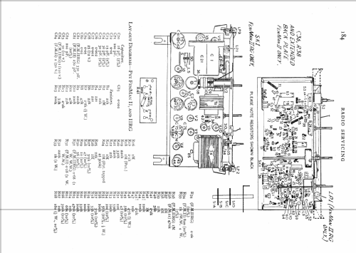
Click on the schematic thumbnail to request the schematic as a free document.
- Number of Tubes
- 11
- Main principle
- Superheterodyne (common); ZF/IF 470 kHz
- Wave bands
- Broadcast, Long Wave and FM or UHF.
- Power type and voltage
- Alternating Current supply (AC) / 200-250 Volt
- Loudspeaker
- Permanent Magnet Dynamic (PDyn) Loudspeaker (moving coil)
- Material
- Wooden case
- from Radiomuseum.org
- Model: Fenman 2 - Pye Ltd., Radio Works;
- Shape
- Tablemodel, low profile (big size).
- Mentioned in
- -- Original-techn. papers.
- Author
- Model page created by Peter Hoddow. See "Data change" for further contributors.
- Other Models
-
Here you find 629 models, 485 with images and 342 with schematics for wireless sets etc. In French: TSF for Télégraphie sans fil.
All listed radios etc. from Pye Ltd., Radio Works; Cambridge
Collections
The model Fenman is part of the collections of the following members.
Forum contributions about this model: Pye Ltd., Radio: Fenman 2
Threads: 1 | Posts: 4
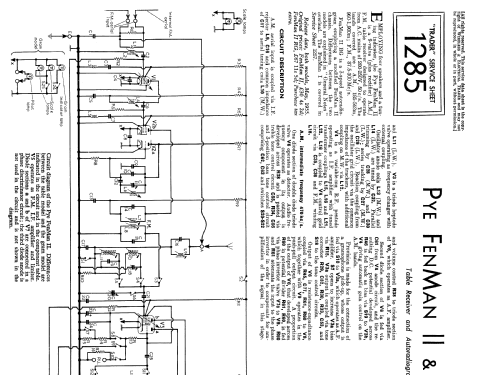
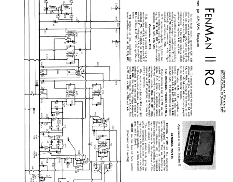
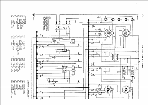
I have just finished uploading the schematics for the Pye FenMan 2, prompted by a friend purchasing an example of this radio and needing the service information for it.
Whilst copying it and studying the FM tuner circuit, which is rather different from the typical double-triode arrangement used in many sets, I noticed that there was no immediately obvious arragement for coupling the oscillations from the triode section of the ECF80 into the pentode section. I assume that there is an internal shield between the two sections and the two sections are electrically isolated, so how does it work? I did wonder if the RF choke in the decoupling of the screen grid of the ECF80 had any bearing on the operation of the mixer? In some television tuners a small value of capacity (ca. 2pF) couples the two sections. Am I missing something obvious here?
I have included an extract of the circuit below, if anyone needs the circuit values I can add those later. All your thoughts are gratefully received!
.png)
Whilst copying it and studying the FM tuner circuit, which is rather different from the typical double-triode arrangement used in many sets, I noticed that there was no immediately obvious arragement for coupling the oscillations from the triode section of the ECF80 into the pentode section. I assume that there is an internal shield between the two sections and the two sections are electrically isolated, so how does it work? I did wonder if the RF choke in the decoupling of the screen grid of the ECF80 had any bearing on the operation of the mixer? In some television tuners a small value of capacity (ca. 2pF) couples the two sections. Am I missing something obvious here?
I have included an extract of the circuit below, if anyone needs the circuit values I can add those later. All your thoughts are gratefully received!
.png)
Mike Izycky, 03.Aug.07
