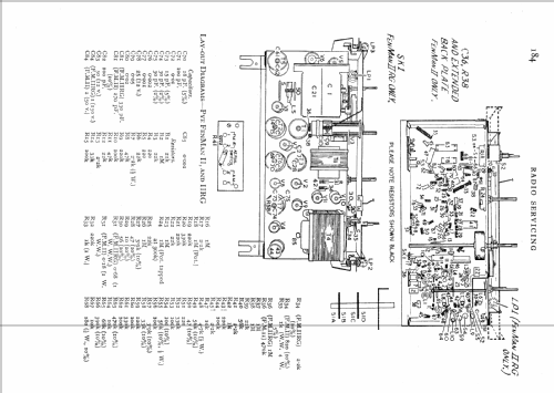
Fenman 2
Pye Ltd., Radio Works; Cambridge
- Land
- Grossbritannien (UK)
- Hersteller / Marke
- Pye Ltd., Radio Works; Cambridge
- Jahr
- 1955
- Kategorie
- Rundfunkempfänger (Radio - oder Tuner nach WW2)
- Radiomuseum.org ID
- 102299
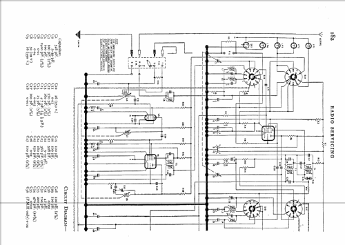
Klicken Sie auf den Schaltplanausschnitt, um diesen kostenlos als Dokument anzufordern.
- Anzahl Röhren
- 11
- Hauptprinzip
- Superhet allgemein; ZF/IF 470 kHz
- Wellenbereiche
- Langwelle, Mittelwelle und UKW (FM).
- Betriebsart / Volt
- Wechselstromspeisung / 200-250 Volt
- Lautsprecher
- Dynamischer LS, keine Erregerspule (permanentdynamisch)
- Material
- Gerät mit Holzgehäuse
- von Radiomuseum.org
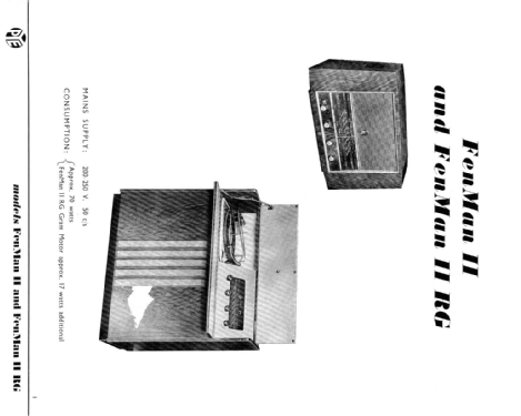
- Modell: Fenman 2 - Pye Ltd., Radio Works;
- Form
- Tischgerät-gross, - Querformat (breiter als hoch oder quadratisch).
- Literaturnachweis
- -- Original-techn. papers.
- Autor
- Modellseite von Peter Hoddow angelegt. Siehe bei "Änderungsvorschlag" für weitere Mitarbeit.
- Weitere Modelle
-
Hier finden Sie 634 Modelle, davon 490 mit Bildern und 342 mit Schaltbildern.
Alle gelisteten Radios usw. von Pye Ltd., Radio Works; Cambridge
Sammlungen
Das Modell Fenman befindet sich in den Sammlungen folgender Mitglieder.
Forumsbeiträge zum Modell: Pye Ltd., Radio: Fenman 2
Threads: 1 | Posts: 4
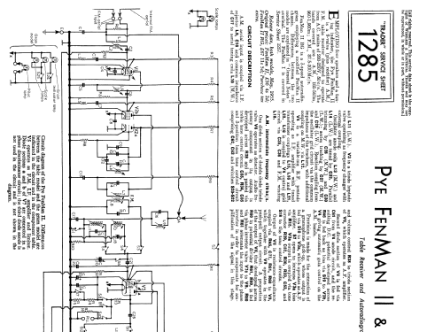
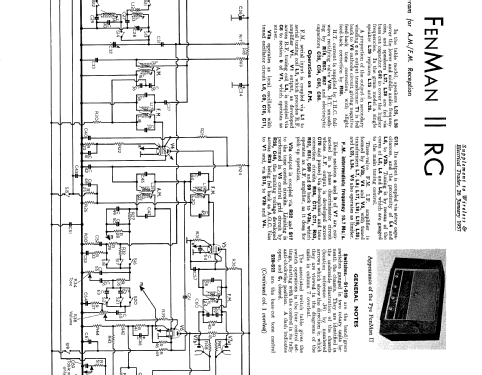
I have just finished uploading the schematics for the Pye FenMan 2, prompted by a friend purchasing an example of this radio and needing the service information for it.
Whilst copying it and studying the FM tuner circuit, which is rather different from the typical double-triode arrangement used in many sets, I noticed that there was no immediately obvious arragement for coupling the oscillations from the triode section of the ECF80 into the pentode section. I assume that there is an internal shield between the two sections and the two sections are electrically isolated, so how does it work? I did wonder if the RF choke in the decoupling of the screen grid of the ECF80 had any bearing on the operation of the mixer? In some television tuners a small value of capacity (ca. 2pF) couples the two sections. Am I missing something obvious here?
I have included an extract of the circuit below, if anyone needs the circuit values I can add those later. All your thoughts are gratefully received!
.png)
Whilst copying it and studying the FM tuner circuit, which is rather different from the typical double-triode arrangement used in many sets, I noticed that there was no immediately obvious arragement for coupling the oscillations from the triode section of the ECF80 into the pentode section. I assume that there is an internal shield between the two sections and the two sections are electrically isolated, so how does it work? I did wonder if the RF choke in the decoupling of the screen grid of the ECF80 had any bearing on the operation of the mixer? In some television tuners a small value of capacity (ca. 2pF) couples the two sections. Am I missing something obvious here?
I have included an extract of the circuit below, if anyone needs the circuit values I can add those later. All your thoughts are gratefully received!
.png)
Mike Izycky, 03.Aug.07
