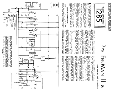
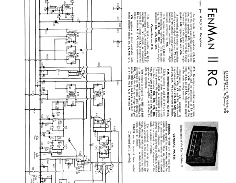
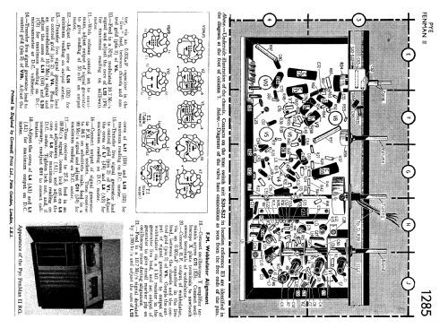
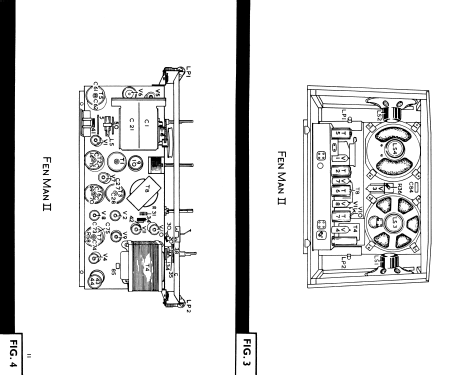
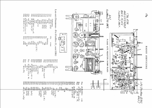
Fenman 2
Pye Ltd., Radio Works; Cambridge
- Pays
- Royaume Uni
- Fabricant / Marque
- Pye Ltd., Radio Works; Cambridge
- Année
- 1955
- Catégorie
- Radio - ou tuner d'après la guerre 1939-45
- Radiomuseum.org ID
- 102299
Cliquez sur la vignette du schéma pour le demander en tant que document gratuit.
- No. de tubes
- 11
- Principe général
- Super hétérodyne (en général); FI/IF 470 kHz
- Gammes d'ondes
- PO, GO et FM
- Tension / type courant
- Alimentation Courant Alternatif (CA) / 200-250 Volt
- Haut-parleur
- HP dynamique à aimant permanent + bobine mobile
- Matière
- Boitier en bois
- De Radiomuseum.org
- Modèle: Fenman 2 - Pye Ltd., Radio Works;
- Forme
- Modèle de table profil bas (grand modèle).
- Littérature
- -- Original-techn. papers.
- Auteur
- Modèle crée par Peter Hoddow. Voir les propositions de modification pour les contributeurs supplémentaires.
- D'autres Modèles
-
Vous pourrez trouver sous ce lien 634 modèles d'appareils, 490 avec des images et 342 avec des schémas.
Tous les appareils de Pye Ltd., Radio Works; Cambridge
Collections
Le modèle Fenman fait partie des collections des membres suivants.
Contributions du forum pour ce modèle: Pye Ltd., Radio: Fenman 2
Discussions: 1 | Publications: 4
I have just finished uploading the schematics for the Pye FenMan 2, prompted by a friend purchasing an example of this radio and needing the service information for it.
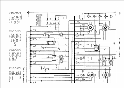
Whilst copying it and studying the FM tuner circuit, which is rather different from the typical double-triode arrangement used in many sets, I noticed that there was no immediately obvious arragement for coupling the oscillations from the triode section of the ECF80 into the pentode section. I assume that there is an internal shield between the two sections and the two sections are electrically isolated, so how does it work? I did wonder if the RF choke in the decoupling of the screen grid of the ECF80 had any bearing on the operation of the mixer? In some television tuners a small value of capacity (ca. 2pF) couples the two sections. Am I missing something obvious here?
I have included an extract of the circuit below, if anyone needs the circuit values I can add those later. All your thoughts are gratefully received!
.png)
Whilst copying it and studying the FM tuner circuit, which is rather different from the typical double-triode arrangement used in many sets, I noticed that there was no immediately obvious arragement for coupling the oscillations from the triode section of the ECF80 into the pentode section. I assume that there is an internal shield between the two sections and the two sections are electrically isolated, so how does it work? I did wonder if the RF choke in the decoupling of the screen grid of the ECF80 had any bearing on the operation of the mixer? In some television tuners a small value of capacity (ca. 2pF) couples the two sections. Am I missing something obvious here?
I have included an extract of the circuit below, if anyone needs the circuit values I can add those later. All your thoughts are gratefully received!
.png)
Mike Izycky, 03.Aug.07
