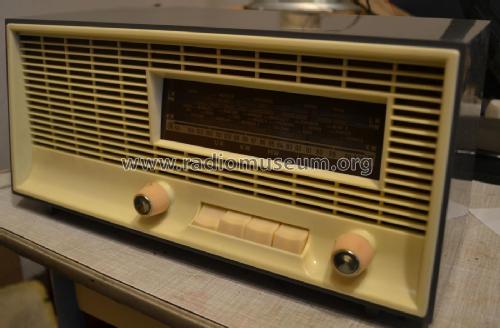
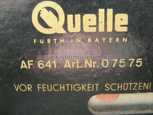
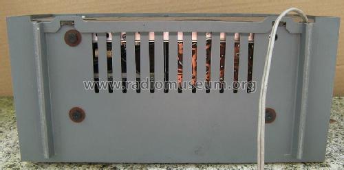
Simonetta-4-Wellen-Super AF641 Art. Nr. 07575
QUELLE GmbH (Universum); Fürth und Nürnberg
- Country
- Germany
- Manufacturer / Brand
- QUELLE GmbH (Universum); Fürth und Nürnberg
- Year
- 1964
- Category
- Broadcast Receiver - or past WW2 Tuner
- Radiomuseum.org ID
- 276013
Click on the schematic thumbnail to request the schematic as a free document.
- Number of Tubes
- 5
- Main principle
- Superheterodyne (common); ZF/IF 455/10700 kHz
- Tuned circuits
- 6 AM circuit(s) 10 FM circuit(s)
- Wave bands
- Broadcast, Long Wave, Short Wave plus FM or UHF.
- Power type and voltage
- AC/DC-set / 220 Volt
- Loudspeaker
- Permanent Magnet Dynamic (PDyn) Loudspeaker (moving coil)
- Material
- Plastics (no bakelite or catalin)
- from Radiomuseum.org
- Model: Simonetta-4-Wellen-Super AF641 Art. Nr. 07575 - QUELLE GmbH Universum; Fürth
- Shape
- Tablemodel with Push Buttons.
- Dimensions (WHD)
- 345 x 169 x 165 mm / 13.6 x 6.7 x 6.5 inch
- Notes
-
Hergestellt von Stern-Radio Sonneberg/RFT für Quelle GmbH.
Siehe auch das technisch identische Modell im Holzgehäuse
Simonetta-4-Wellen-Super AF642 Art. Nr. 07576
- Literature/Schematics (1)
- -- Original-techn. papers.
- Author
- Model page created by Wolfgang Bauer. See "Data change" for further contributors.
- Other Models
-
Here you find 1088 models, 912 with images and 514 with schematics for wireless sets etc. In French: TSF for Télégraphie sans fil.
All listed radios etc. from QUELLE GmbH (Universum); Fürth und Nürnberg
Collections
The model Simonetta-4-Wellen-Super is part of the collections of the following members.
Forum contributions about this model: QUELLE GmbH: Simonetta-4-Wellen-Super AF641 Art. Nr. 07575
Threads: 2 | Posts: 5
Hi,
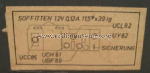
Does anyone know the value of the two festoon panel lamp bulbs for the Simonetta-4-Wellen-Super AF641 Art. Nr. 07575
Both are missing, so I have no idea what they should be, and it's not marked on the schematic, as this set has series heaters, they could be any value depending on the circuit designer. As it looks like there is 24V accross the pair, I'm guessing they are 12V, but what wattage?
Chris Walter, 05.Aug.22
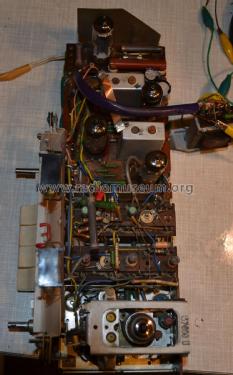
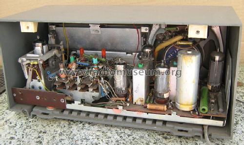
Hier wird die UBF89 links von der Gleichrichterröhre UY82 eingesetzt und nicht wie sonst üblich und wie auch im Schaltplan ausgewiesen, die UCL82. Mir ist leider der Fehler unterlaufen.
Das Gerät ist ein Allströmer und verfügt über keinen Netzrafo.
Norbert Meyer, 19.May.18


