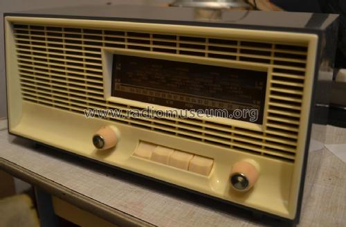
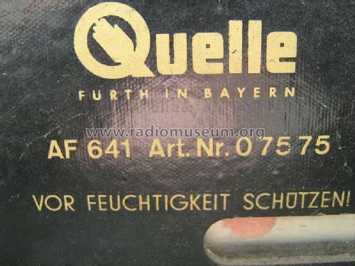
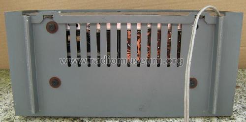
Simonetta-4-Wellen-Super AF641 Art. Nr. 07575
QUELLE GmbH (Universum); Fürth und Nürnberg
- Paese
- Germania
- Produttore / Marca
- QUELLE GmbH (Universum); Fürth und Nürnberg
- Anno
- 1964
- Categoria
- Radio (o sintonizzatore del dopoguerra WW2)
- Radiomuseum.org ID
- 276013
Clicca sulla miniatura dello schema per richiederlo come documento gratuito.
- Numero di tubi
- 5
- Principio generale
- Supereterodina (in generale); ZF/IF 455/10700 kHz
- N. di circuiti accordati
- 6 Circuiti Mod. Amp. (AM) 10 Circuiti Mod. Freq. (FM)
- Gamme d'onda
- Onde medie (OM), lunghe (OL), corte (OC) e MF (FM).
- Tensioni di funzionamento
- Alimentazione universale (doppia: CC/CA) / 220 Volt
- Altoparlante
- AP magnetodinamico (magnete permanente e bobina mobile)
- Materiali
- Plastica (non bachelite o catalina)
- Radiomuseum.org
- Modello: Simonetta-4-Wellen-Super AF641 Art. Nr. 07575 - QUELLE GmbH Universum; Fürth
- Forma
- Soprammobile con pulsantiera/tastiera.
- Dimensioni (LxAxP)
- 345 x 169 x 165 mm / 13.6 x 6.7 x 6.5 inch
- Annotazioni
-
Hergestellt von Stern-Radio Sonneberg/RFT für Quelle GmbH.
Siehe auch das technisch identische Modell im Holzgehäuse
Simonetta-4-Wellen-Super AF642 Art. Nr. 07576
- Letteratura / Schemi (1)
- -- Original-techn. papers.
- Autore
- Modello inviato da Wolfgang Bauer. Utilizzare "Proponi modifica" per inviare ulteriori dati.
- Altri modelli
-
In questo link sono elencati 1092 modelli, di cui 916 con immagini e 518 con schemi.
Elenco delle radio e altri apparecchi della QUELLE GmbH (Universum); Fürth und Nürnberg
Collezioni
Il modello Simonetta-4-Wellen-Super fa parte delle collezioni dei seguenti membri.
Discussioni nel forum su questo modello: QUELLE GmbH: Simonetta-4-Wellen-Super AF641 Art. Nr. 07575
Argomenti: 2 | Articoli: 5
Hi,
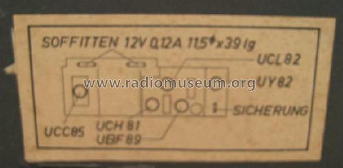
Does anyone know the value of the two festoon panel lamp bulbs for the Simonetta-4-Wellen-Super AF641 Art. Nr. 07575
Both are missing, so I have no idea what they should be, and it's not marked on the schematic, as this set has series heaters, they could be any value depending on the circuit designer. As it looks like there is 24V accross the pair, I'm guessing they are 12V, but what wattage?
Chris Walter, 05.Aug.22
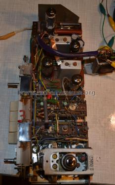
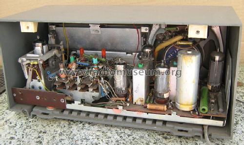
Hier wird die UBF89 links von der Gleichrichterröhre UY82 eingesetzt und nicht wie sonst üblich und wie auch im Schaltplan ausgewiesen, die UCL82. Mir ist leider der Fehler unterlaufen.
Das Gerät ist ein Allströmer und verfügt über keinen Netzrafo.
Norbert Meyer, 19.May.18


