FM Tuner Chrome CHASSIS
Scott Radio Labs.(E.H., Transformer); Chicago (IL)
- Land
- USA
- Hersteller / Marke
- Scott Radio Labs.(E.H., Transformer); Chicago (IL)
- Jahr
- 1940
- Kategorie
- Vorsatzgerät (Adapter für KW/UKW/VHF/UHF inkl. Einbaugerät), Konverter
- Radiomuseum.org ID
- 55364

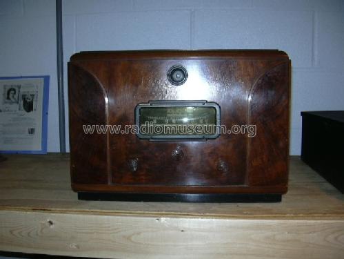
Scott FM Tuner in Mode Cabinet
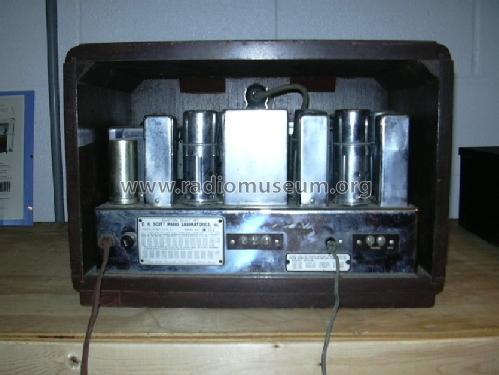
Scott FM Tuner - inside view

Klicken Sie auf den Schaltplanausschnitt, um diesen kostenlos als Dokument anzufordern.
- Anzahl Röhren
- 10
- Hauptprinzip
- Superhet allgemein
- Wellenbereiche
- UKW-Gerät bzw. FM (keine weiteren Bänder).
- Betriebsart / Volt
- Wechselstromspeisung / 110 Volt
- Lautsprecher
- - Für Kopfhörer oder NF-Verstärker
- Material
- Metall, SICHTBARE RÖHREN
- von Radiomuseum.org
- Modell: FM Tuner Chrome CHASSIS - Scott Radio Labs.E.H.,
- Form
- Chassis - Einbaugerät
- Bemerkung
- Old FM band 41-50 MHz.
Price with table cabinet 120 USD. Special cabinet Mod'e.
- Originalpreis
- 110.00 $
- Datenherkunft extern
- Ernst Erb
- Datenherkunft
- Guide to Old Radios
- Schaltungsnachweis
- Rider's Perpetual, Volume 14 = 1944 = before 1943
- Literaturnachweis
- E.H.Scott Radio Collectors Guide (1925-1946) (.)
- Literatur/Schema (1)
- Scotts new Silver Ghosts
- Literatur/Schema (2)
- Pre-War Consoles
- Weitere Modelle
-
Hier finden Sie 201 Modelle, davon 126 mit Bildern und 51 mit Schaltbildern.
Alle gelisteten Radios usw. von Scott Radio Labs.(E.H., Transformer); Chicago (IL)
Sammlungen
Das Modell FM Tuner befindet sich in den Sammlungen folgender Mitglieder.
Forumsbeiträge zum Modell: Scott Radio Labs.E.H: FM Tuner Chrome CHASSIS
Threads: 1 | Posts: 1
The Scott FM tuner starts with an 1853 high Gm tube as the RF amplifier. The output is transformer coupled to the mixer, a 6SA7 tube. The triode section of the 6SA7 is used as the local oscillator. A VR150 regulator stabilizes the oscillator plate supply, providing a stable IF output at 5.25 MHz. The IF amplification is passed through four stages. The first two stages are type 1232 high Gm tubes. The IF coupling is unique, using a combination of inductive tuning and capacitive coupling to minimize inductive coupling in the IF transformers. The third and fourth stages are generally referred to as the first and second limiters. This function is obtained from two 6J7 tubes, in a cascade limiter circuit. The grid-leak condenser combinations used in these stages determine the noise limiting time constants. The first limiter has a time constant of 2.5 microseconds. The second stage is at half that value. The discriminator/detector is a 6H6 dual diode. With a well balanced diode pair, the detector circuit should have a uniform response from 30 to 15000 cycles. The R/C circuit following the diode load is a correction for pre-emphasis of high audio frequencies imposed at the transmitter. Finally, a 6E5 tuning indicator is fed through a voltage divider/audio filter from the second limiter stage. The stand alone FM tuner unit has a 5Y3 rectifier for the power supply.
Kent King, 22.Aug.06