FM Tuner Chrome CHASSIS
Scott Radio Labs.(E.H., Transformer); Chicago (IL)
- Pays
- Etats-Unis
- Fabricant / Marque
- Scott Radio Labs.(E.H., Transformer); Chicago (IL)
- Année
- 1940
- Catégorie
- Adaptateur ou convertisseur de fréquences (OC/MF/VHF/UFH)
- Radiomuseum.org ID
- 55364

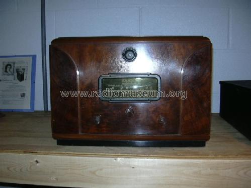
Scott FM Tuner in Mode Cabinet
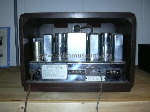
Scott FM Tuner - inside view

Cliquez sur la vignette du schéma pour le demander en tant que document gratuit.
- No. de tubes
- 10
- Principe général
- Super hétérodyne (en général)
- Gammes d'ondes
- FM uniquement
- Tension / type courant
- Alimentation Courant Alternatif (CA) / 110 Volt
- Haut-parleur
- - Pour casque ou amplificateur BF
- Matière
- Boitier métallique, lampes visibles
- De Radiomuseum.org
- Modèle: FM Tuner Chrome CHASSIS - Scott Radio Labs.E.H.,
- Forme
- Chassis (pour intégration dans meuble)
- Remarques
- Old FM band 41-50 MHz.
Price with table cabinet 120 USD. Special cabinet Mod'e.
- Prix de mise sur le marché
- 110.00 $
- Source extérieure
- Ernst Erb
- Source
- Guide to Old Radios
- Source du schéma
- Rider's Perpetual, Volume 14 = 1944 = before 1943
- Littérature
- E.H.Scott Radio Collectors Guide (1925-1946) (.)
- Schémathèque (1)
- Scotts new Silver Ghosts
- Schémathèque (2)
- Pre-War Consoles
- D'autres Modèles
-
Vous pourrez trouver sous ce lien 201 modèles d'appareils, 126 avec des images et 51 avec des schémas.
Tous les appareils de Scott Radio Labs.(E.H., Transformer); Chicago (IL)
Contributions du forum pour ce modèle: Scott Radio Labs.E.H: FM Tuner Chrome CHASSIS
Discussions: 1 | Publications: 1
The Scott FM tuner starts with an 1853 high Gm tube as the RF amplifier. The output is transformer coupled to the mixer, a 6SA7 tube. The triode section of the 6SA7 is used as the local oscillator. A VR150 regulator stabilizes the oscillator plate supply, providing a stable IF output at 5.25 MHz. The IF amplification is passed through four stages. The first two stages are type 1232 high Gm tubes. The IF coupling is unique, using a combination of inductive tuning and capacitive coupling to minimize inductive coupling in the IF transformers. The third and fourth stages are generally referred to as the first and second limiters. This function is obtained from two 6J7 tubes, in a cascade limiter circuit. The grid-leak condenser combinations used in these stages determine the noise limiting time constants. The first limiter has a time constant of 2.5 microseconds. The second stage is at half that value. The discriminator/detector is a 6H6 dual diode. With a well balanced diode pair, the detector circuit should have a uniform response from 30 to 15000 cycles. The R/C circuit following the diode load is a correction for pre-emphasis of high audio frequencies imposed at the transmitter. Finally, a 6E5 tuning indicator is fed through a voltage divider/audio filter from the second limiter stage. The stand alone FM tuner unit has a 5Y3 rectifier for the power supply.
Kent King, 22.Aug.06