FM radio altimeter STR30
Standard Telephones and Cables Ltd. (STC); London, Foots Cray
- Country
- Great Britain (UK)
- Manufacturer / Brand
- Standard Telephones and Cables Ltd. (STC); London, Foots Cray
- Year
- 1951
- Category
- RADAR equipment
- Radiomuseum.org ID
- 304053
-
- Brand: Micromesh tubes
Manufacturer's documentation
Manufacturer's documentation
Manufacturer's documentation
Manufacturer's documentation
Manufacturer's documentation
Manufacturer's documentation
Manufacturer's documentation
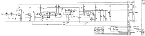
Click on the schematic thumbnail to request the schematic as a free document.
- Number of Tubes
- 31
- Number of Transistors
- Wave bands
- Wave Bands given in the notes.
- Power type and voltage
- Powered by external power supply or a main unit.
- Material
- Metal case
- from Radiomuseum.org
- Model: FM radio altimeter STR30 - Standard Telephones and Cables
- Notes
-
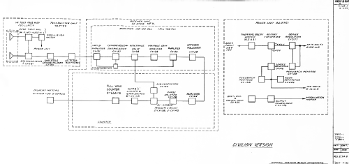
The Type STR30 is an S band (7 cm) FM radio altimeter that was developed by the Radio Division of Standard Telephones and Cables Ltd at New Southgate, London. It was used as part of the Royal Aircraft Establishment's BLEU (Blind Landing Experimental Unit) programme to provide the precise height-above-ground information required for the automatic landing of an aircraft in zero visibility. The information was used to control the aircraft approach speed and flare-out.
Minimum height: 0 ft.
Maximum height: 5000 ft.
Accuracy: Error does not exceed +-2 ft or +-3%, whichever is the greater.
Transmitter frequency: In band 4200 - 4400 MHz.
Sweep on low range: 100 MHz.
Sweep on high range: 10 MHz.
Transmitter power: 0.5 W to antenna.
Modulation: 300 Hz by 4 W 3-phase synchronous hysteresis motor.
Receiver mixer: Balanced silicon diode mixer.
Overall amplification: >100 dB.
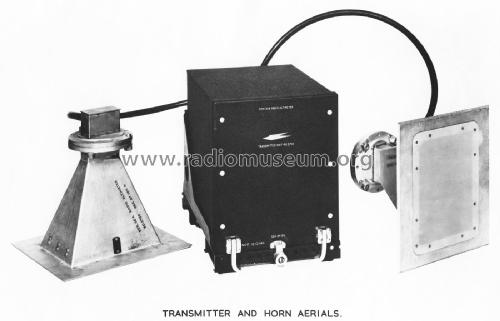
Counter output: 4 mA.Antennas: Flush-mounting horns with fibreglass covers.
Maximum angle of bank +-20 deg.
Maximum angle of pitch +-17 deg.
There are very small sidelobes at 90 deg.
Isolation between transmit and receive antennas: 50 dB.
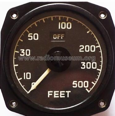
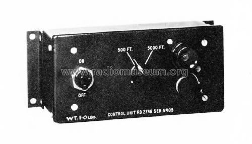
VSWR <1.12 over the 200 MHz band.Indicators: 0-500 ft with log scale for approach and landing, 0-5000 ft with linear scale for normal flight use.
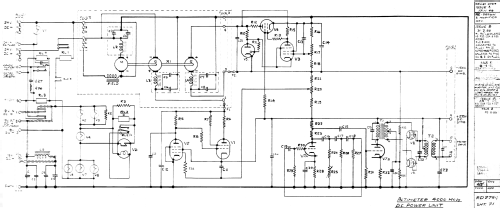
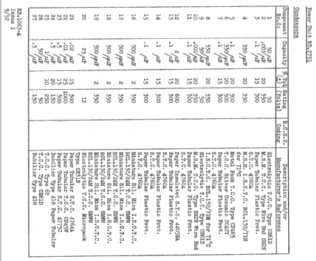
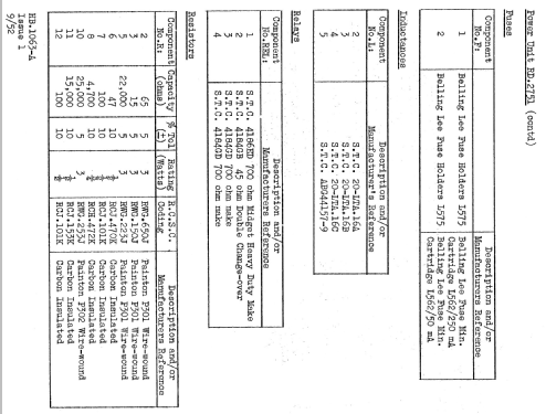
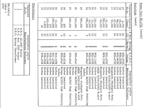
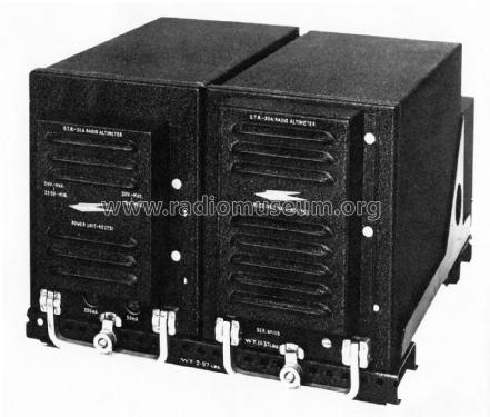
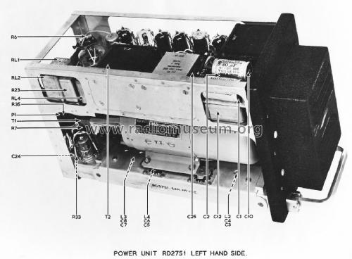
Remote control unit for pilot.A power unit delivers stabilised HT and bias supplies, together with 300 Hz for the modulation motor.
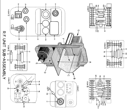
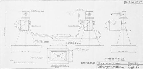
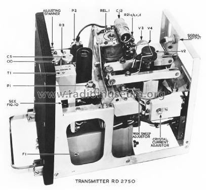
The inputs to the power supply are 23.5 - 29v DC at 9A and 19v stabilised at 3A.The transmitter is housed in a 7" SBAC rack with a special backplate carrying a receiver coupling waveguide, an adjustable transmitter coupling probe, and two permanently mounted 30" (76 cm) UR21 RF cables for the antennas. There is an attenuation of about 0.8 dB in each cable. The delay in these cables and the waveguide results in a signal of about 1 kHz on the 500 ft range,which is the minimum possible signal frequency.
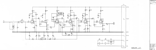
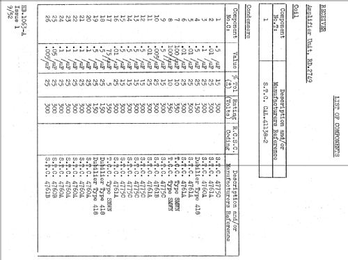
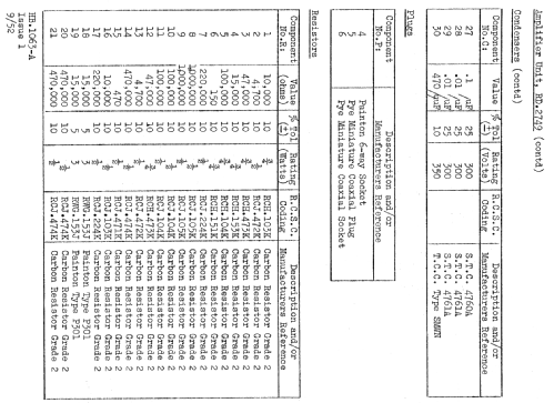
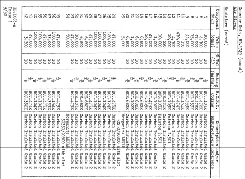
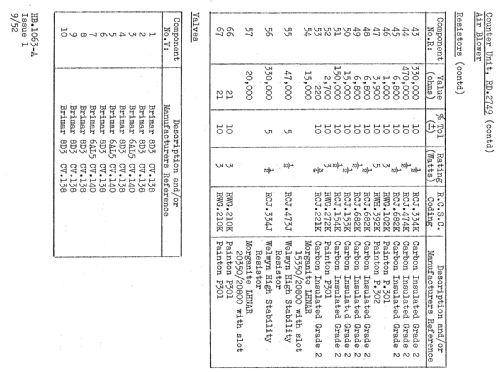
The receiver and power supply units are housed in a standard SBAC rack.Valve complement:
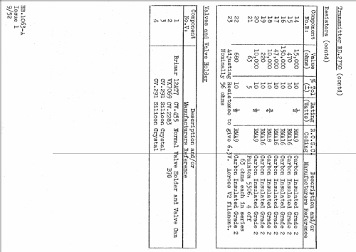
Transmitter
VX7069
12AT7
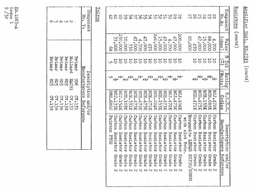
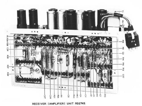
2 CV291Receiver - amplifier unit
4 8D3
9D6
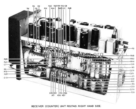
EAC91Receiver - counter unit
7 8D3
3 6AL5
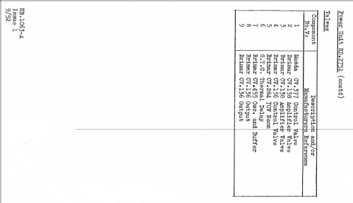
2 CG4CPower unit
3 7D9
2 8D3
12AT7
V1135
STV70/20
VLS631
- Net weight (2.2 lb = 1 kg)
- 20.4 kg / 44 lb 14.9 oz (44.934 lb)
- Author
- Model page created by Bruce Taylor. See "Data change" for further contributors.
- Other Models
-
Here you find 39 models, 34 with images and 11 with schematics for wireless sets etc. In French: TSF for Télégraphie sans fil.
All listed radios etc. from Standard Telephones and Cables Ltd. (STC); London, Foots Cray
Collections
The model FM radio altimeter is part of the collections of the following members.