- Hersteller / Marke
- Telefunken Deutschland (TFK), (Gesellschaft für drahtlose Telegraphie Telefunken mbH
- Jahr
- 1954/1955
- Kategorie
- Rundfunkempfänger (Radio - oder Tuner nach WW2)
- Radiomuseum.org ID
- 19633


angelitos2004 320614165053
angelitos2004 320614165053

Opus logo is missing


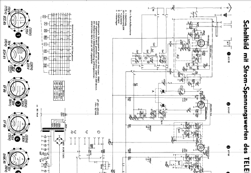
Klicken Sie auf den Schaltplanausschnitt, um diesen kostenlos als Dokument anzufordern.
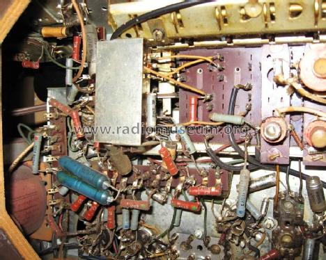
- Anzahl Röhren
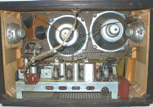
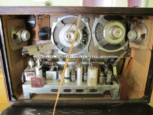
- 9
- Anzahl Transistoren
- Halbleiter
- B250C140
- Hauptprinzip
- Superhet allgemein; ZF/IF 460/10700 kHz
- Anzahl Kreise
- 8 Kreis(e) AM 11 Kreis(e) FM
- Wellenbereiche
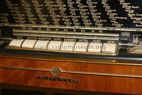
- Langwelle, Mittelwelle, Kurzwelle und UKW.
- Betriebsart / Volt
- Wechselstromspeisung / 110, 125, 150, 220, 240 Volt
- Lautsprecher
- 6 Lautsprecher
- Belastbarkeit / Leistung
- 15 W (Qualität unbekannt)
- Material
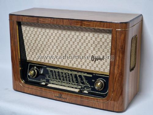
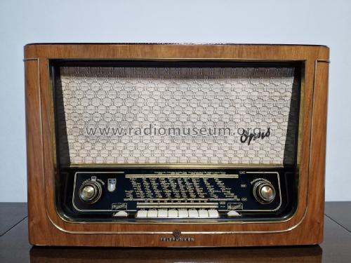
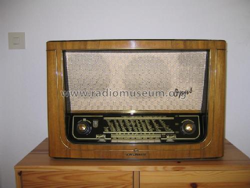
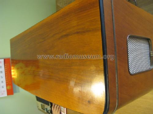
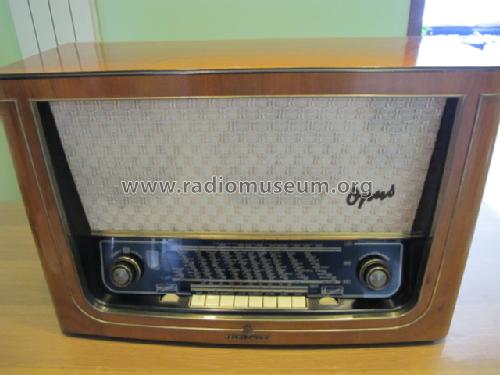
- Gerät mit Holzgehäuse
Die GFGF Zeitschrift Funkgeschichte bringt interessante Artikel zu Radios, Funkwesen und Medien. Bei Radiomuseum.org finden Sie die vollständigen Hefte früherer Ausgaben als PDF zum Download.
- von Radiomuseum.org
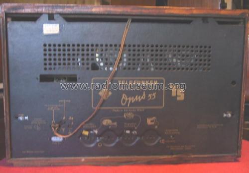
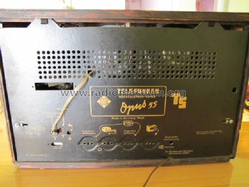
- Modell: Opus 55/TS - Telefunken Deutschland TFK,
- Form
- Tischgerät, Tasten oder Druckknöpfe.
- Abmessungen (BHT)
- 640 x 420 x 280 mm / 25.2 x 16.5 x 11 inch
- Bemerkung
-
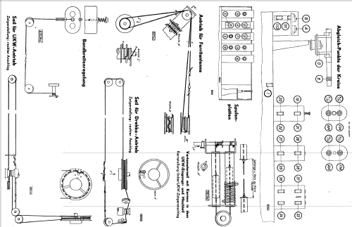
Regelbare Bandbreite, KW-Lupe;
Chassis baugleich mit AEG 3084WD.
See export Versions with and without side speakers.
- Originalpreis
- 489.00 DM
- Datenherkunft extern
- Erb
- Datenherkunft
- Rundfunk- und Fernseh-Katalog 1954/55
- Literaturnachweis
- HdB d.Rdf-& Ferns-GrH 1954/55 (S.69)
- Literatur/Schema (1)
- Radio und Fernsehen (DDR) (11-1954, Seite 323)
- Literatur/Schema (2)
- -- Original-techn. papers.
- Weitere Modelle
-
Hier finden Sie 3580 Modelle, davon 3167 mit Bildern und 2123 mit Schaltbildern.
Alle gelisteten Radios usw. von Telefunken Deutschland (TFK), (Gesellschaft für drahtlose Telegraphie Telefunken mbH
Sammlungen
Das Modell Opus befindet sich in den Sammlungen folgender Mitglieder.
Forumsbeiträge zum Modell: Telefunken: Opus 55/TS
Threads: 1 | Posts: 15
Respected Members,
Restoring my Opus 55 TS the new magical eye illuminates lightly. The B + is 40 volt low the normal value. The Selenium rectifier is very old and I replaced its contained with four silicon diodes 1N4007 forming a bridge with four 4.7 nf capacitors in parallel to each diode. To adjust the B+ value I put a 220 ohms 10 watts resistors in series with the power transformer. Now the B + is in normal value and the EM80 glow well.
But during the first and half minute, after power on the radio, the B + rises to 340-360 volts and slowly reaches the normal value. I understand that is a characteristic of the Silicon rectifiers and not in the selenium rectifiers.
This abrupt increase of voltage can be dangerous for other components of the radio as power capacitors, output transformer or output valves? It is necessary to control this abrupt increase of tension?
Thanks in advance,
Bruno.
Bruno Gandolfo-Canepa, 15.Feb.06