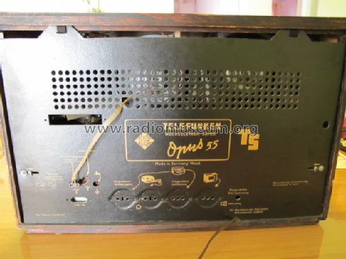
- Country
- Germany
- Manufacturer / Brand
- Telefunken Deutschland (TFK), (Gesellschaft für drahtlose Telegraphie Telefunken mbH
- Year
- 1954/1955
- Category
- Broadcast Receiver - or past WW2 Tuner
- Radiomuseum.org ID
- 19633
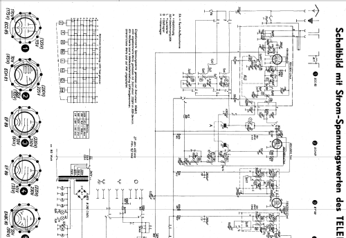
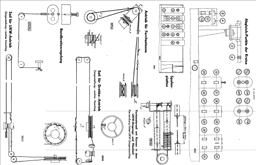
Click on the schematic thumbnail to request the schematic as a free document.
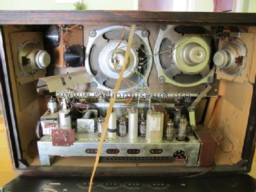
- Number of Tubes
- 9
- Number of Transistors
- Semiconductors
- B250C140
- Main principle
- Superheterodyne (common); ZF/IF 460/10700 kHz
- Tuned circuits
- 8 AM circuit(s) 11 FM circuit(s)
- Wave bands
- Broadcast, Long Wave, Short Wave plus FM or UHF.
- Power type and voltage
- Alternating Current supply (AC) / 110, 125, 150, 220, 240 Volt
- Loudspeaker
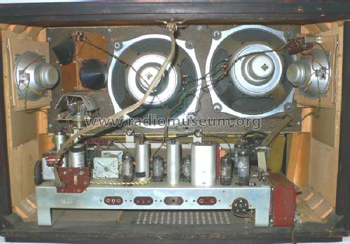
- 6 Loudspeakers
- Power out
- 15 W (unknown quality)
- Material
- Wooden case
- from Radiomuseum.org
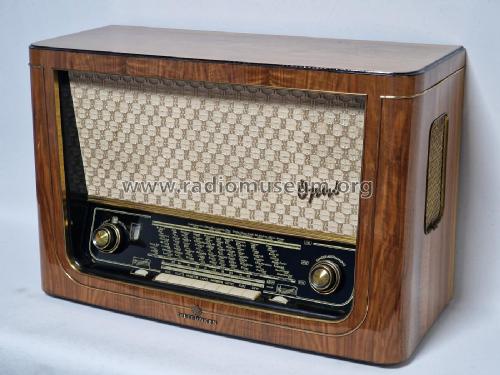
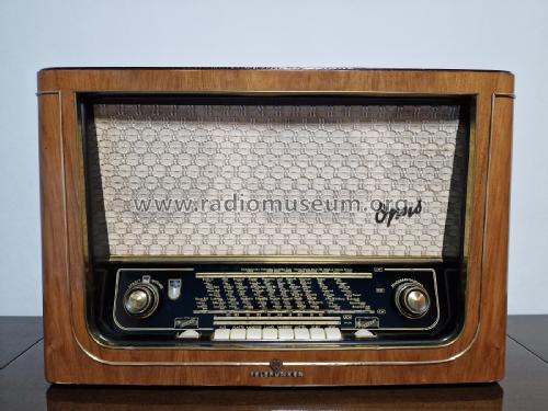
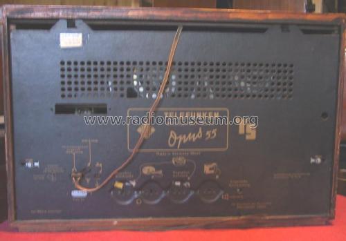
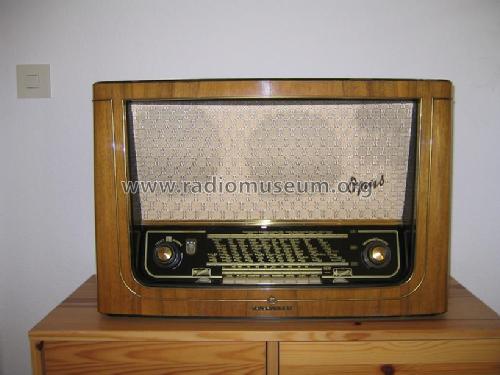
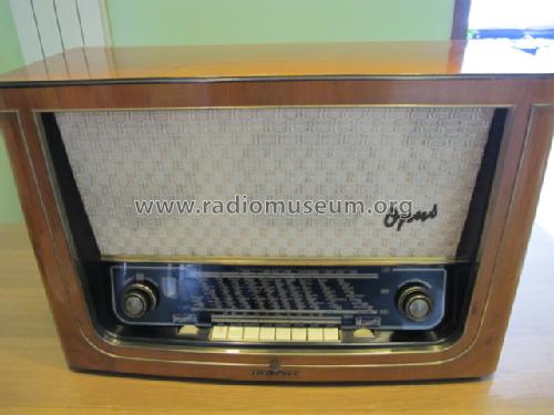
- Model: Opus 55/TS - Telefunken Deutschland TFK,
- Shape
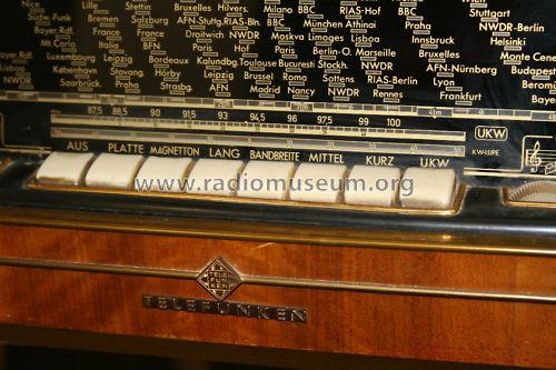
- Tablemodel with Push Buttons.
- Dimensions (WHD)
- 640 x 420 x 280 mm / 25.2 x 16.5 x 11 inch
- Notes
-
Regelbare Bandbreite, KW-Lupe;
Chassis baugleich mit AEG 3084WD.
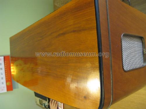
See export Versions with and without side speakers.
- Price in first year of sale
- 489.00 DM
- External source of data
- Erb
- Source of data
- Rundfunk- und Fernseh-Katalog 1954/55
- Mentioned in
- HdB d.Rdf-& Ferns-GrH 1954/55 (S.69)
- Literature/Schematics (1)
- Radio und Fernsehen (DDR) (11-1954, Seite 323)
- Literature/Schematics (2)
- -- Original-techn. papers.
- Other Models
-
Here you find 3576 models, 3163 with images and 2121 with schematics for wireless sets etc. In French: TSF for Télégraphie sans fil.
All listed radios etc. from Telefunken Deutschland (TFK), (Gesellschaft für drahtlose Telegraphie Telefunken mbH
Collections
The model Opus is part of the collections of the following members.
Forum contributions about this model: Telefunken: Opus 55/TS
Threads: 1 | Posts: 15
Respected Members,
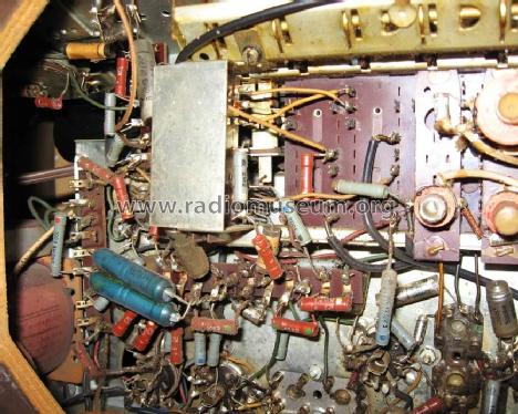
Restoring my Opus 55 TS the new magical eye illuminates lightly. The B + is 40 volt low the normal value. The Selenium rectifier is very old and I replaced its contained with four silicon diodes 1N4007 forming a bridge with four 4.7 nf capacitors in parallel to each diode. To adjust the B+ value I put a 220 ohms 10 watts resistors in series with the power transformer. Now the B + is in normal value and the EM80 glow well.
But during the first and half minute, after power on the radio, the B + rises to 340-360 volts and slowly reaches the normal value. I understand that is a characteristic of the Silicon rectifiers and not in the selenium rectifiers.
This abrupt increase of voltage can be dangerous for other components of the radio as power capacitors, output transformer or output valves? It is necessary to control this abrupt increase of tension?
Thanks in advance,
Bruno.
Bruno Gandolfo-Canepa, 15.Feb.06

