University Sweep & Marker Generator TVR/SM
University / University Graham Instruments Pty. Ltd., Radio Equipment Pty. Ltd.; Sydney
- Pays
- Australie
- Fabricant / Marque
- University / University Graham Instruments Pty. Ltd., Radio Equipment Pty. Ltd.; Sydney
- Année
- 1962 ??
- Catégorie
- Appareils de mesure et de dépannage (matériel de labo)
- Radiomuseum.org ID
- 359391
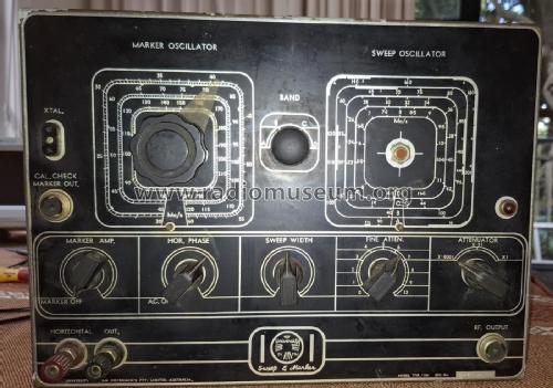
Front panel
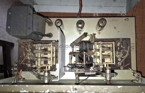
top view
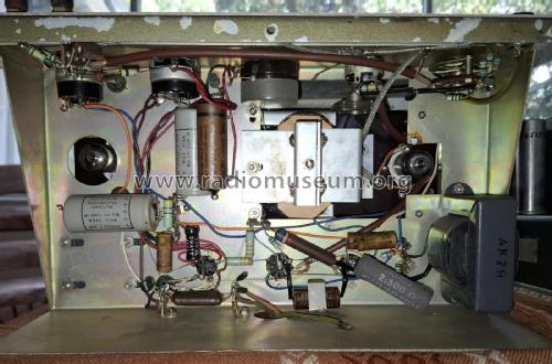
from underneath
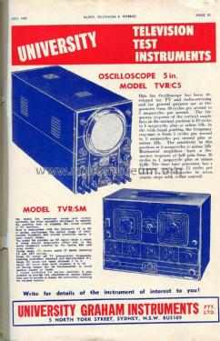
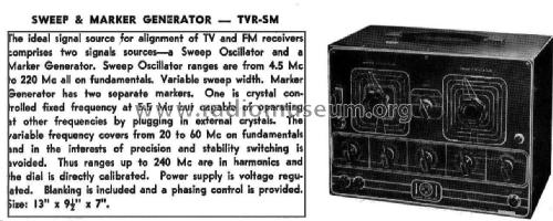
Catalogue c1960. Credit Kevin Chant.
- No. de tubes
- 5
- Lampes / Tubes
- Gammes d'ondes
- Bandes en notes
- Tension / type courant
- Alimentation Courant Alternatif (CA) / 240 Volt
- Haut-parleur
- - - Pas de sortie basse fréquence
- Matière
- Boitier métallique
- De Radiomuseum.org
- Modèle: University Sweep & Marker Generator TVR/SM - University / University Graham
- Forme
- Modèle de table générique
- Dimensions (LHP)
- 13 x 9.5 x 7 inch / 330 x 241 x 178 mm
- Remarques
-
The University Sweep & Marker Generator TVR/SM is a testing device designed for signal generation and frequency analysis of television and FM receivers.
This instrument integrates two key components: sweep and marker generators.The sweep generator produces a signal that varies in frequency from 4.5 MHz to 220 MHz, covering all fundamental frequencies. It features an adjustable sweep width, allowing precise control over the analysed frequency range.
The marker generator consists of two distinct markers:
- A crystal-controlled marker fixed at 5.5 MHz, with the option to use external crystals for other frequencies.
- A variable marker that operates from 20 to 60 MHz on fundamentals, with ranges extending up to 240 MHz using harmonics. This marker dial is directly calibrated for ease of use.
The instrument generates an RF signal that sweeps several MHz on either side of a centre frequency, which is selected using the tuning dial and range switch. The tuning ranges are organized as follows:
- Range 1: Covers sound IF bands, including 5.5 and 10.7 MHz.
- Range 2: Encompasses all TV standard and non-standard IF frequencies.
- Range 3: Spans low band channels 1 to 3.
- Range 4: Covers high band channels 4 to 10.
Operation;
A sweep generator is typically connected to a Cathode Ray Oscilloscope in the following manner:
- The RF output of the sweep generator is connected to the input of the circuit under test.
- The detector output of the circuit under test is then connected to the vertical input of the oscilloscope.
- The sweep generator's horizontal output (often a ramp signal or gate signal) is connected to the external horizontal input of the oscilloscope.
- This setup allows the oscilloscope to display the frequency response of the circuit under test as the sweep generator varies its output frequency. The horizontal axis of the oscilloscope display represents frequency, while the vertical axis shows the amplitude response of the circuit
This versatile device is particularly useful for aligning IF stages in televisions and FM receivers.
- Source
- - - Manufacturers Literature
- Littérature
- - - Manufacturers Literature (University Graham Instruments Pty.,Catalogue c1960)
- Auteur
- Modèle crée par Gordon Markwart. Voir les propositions de modification pour les contributeurs supplémentaires.
- D'autres Modèles
-
Vous pourrez trouver sous ce lien 25 modèles d'appareils, 25 avec des images et 6 avec des schémas.
Tous les appareils de University / University Graham Instruments Pty. Ltd., Radio Equipment Pty. Ltd.; Sydney
Collections
Le modèle University Sweep & Marker Generator fait partie des collections des membres suivants.