- Land
- USA
- Hersteller / Marke
- Wilcox-Gay Corp.; Charlotte (MI)
- Jahr
- 1936 ?
- Kategorie
- Rundfunkempfänger (Radio - oder Tuner nach WW2)
- Radiomuseum.org ID
- 166426
-
- Marke: Recordio
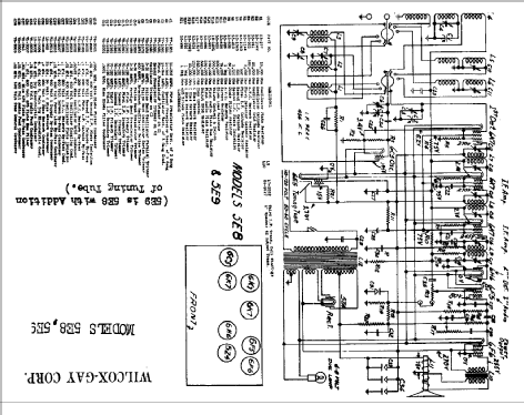
Klicken Sie auf den Schaltplanausschnitt, um diesen kostenlos als Dokument anzufordern.
- Anzahl Röhren
- 8
- Hauptprinzip
- Superhet allgemein; ZF/IF 456 kHz
- Anzahl Kreise
- 9 Kreis(e) AM
- Wellenbereiche
- Mittelwelle, Kurzwelle und Tropenband.
- Betriebsart / Volt
- Wechselstromspeisung / 110-120 Volt
- Lautsprecher
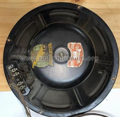
- Dynamischer LS, mit Erregerspule (elektrodynamisch) / Ø 8 inch = 20.3 cm
- von Radiomuseum.org
- Modell: 5E9 - Wilcox-Gay Corp.; Charlotte MI
- Datenherkunft
- Rider's Perpetual, Volume 7 = 1936 and before
- Literatur/Schema (1)
- Riders 7-5
- Autor
- Modellseite von Dirk Taekels angelegt. Siehe bei "Änderungsvorschlag" für weitere Mitarbeit.
- Weitere Modelle
-
Hier finden Sie 241 Modelle, davon 123 mit Bildern und 194 mit Schaltbildern.
Alle gelisteten Radios usw. von Wilcox-Gay Corp.; Charlotte (MI)
Sammlungen
Das Modell 5E9 befindet sich in den Sammlungen folgender Mitglieder.
Forumsbeiträge zum Modell: Wilcox-Gay Corp.;: 5E9
Threads: 1 | Posts: 1
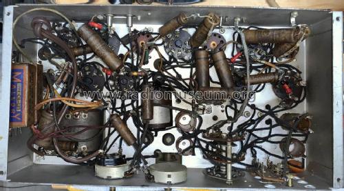
I have owned this console for more than 50 years. Last time it was powered ON must have been 35 years ago. My grand kids want to hear it work so time to restore it. The chassis has no model number. In the pre-internet era it was impossible to identify this 1936 radio. Now I have done that by comparing tube type and layout.
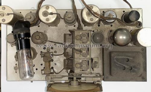
The radio is essentially untouched as shown in the pictures, but many years ago I restored the cabinit to original condition.
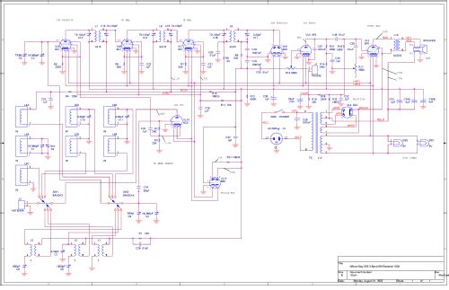
The available schematic from Riders leaves much to the imagination. I have recreated the schematic in OrCad Layout as accurately as I can. Any errors I would appreciate hearing about. This will be challenging becaues I expect all capacitors are bad. If it is appropriate, I will post more pregress pictures.
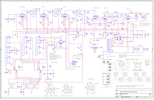
I have updated the schematic to include component locations on the chassis as well as fixing some errors from interpreting the Rider schematic.
I had to remove ALL capacitors and resistors. All resistors were at least 50% high!
Kevin O'Connor, 01.Aug.22
