- País
- Estados Unidos
- Fabricante / Marca
- Wilcox-Gay Corp.; Charlotte (MI)
- Año
- 1936 ?
- Categoría
- Radio - o Sintonizador pasado WW2
- Radiomuseum.org ID
- 166426
-
- Brand: Recordio
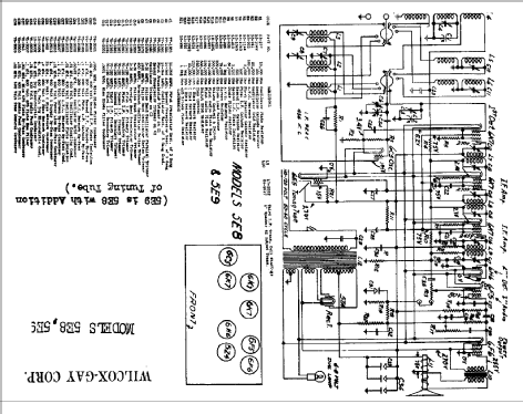
Haga clic en la miniatura esquemática para solicitarlo como documento gratuito.
- Numero de valvulas
- 8
- Principio principal
- Superheterodino en general; ZF/IF 456 kHz
- Número de circuitos sintonía
- 9 Circuíto(s) AM
- Gama de ondas
- OM, OC y banda Pesquera (policia USA)
- Tensión de funcionamiento
- Red: Corriente alterna (CA, Inglés = AC) / 110-120 Volt
- Altavoz
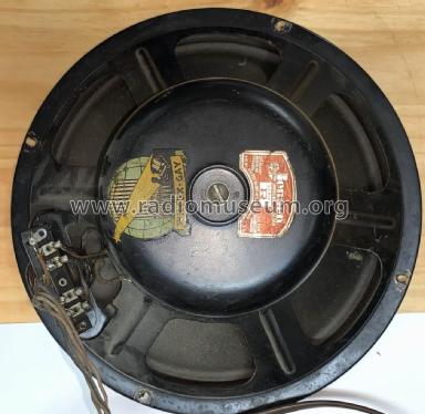
- Altavoz electrodinámico (bobina de campo) / Ø 8 inch = 20.3 cm
- de Radiomuseum.org
- Modelo: 5E9 - Wilcox-Gay Corp.; Charlotte MI
- Procedencia de los datos
- Rider's Perpetual, Volume 7 = 1936 and before
- Documentación / Esquemas (1)
- Riders 7-5
- Autor
- Modelo creado por Dirk Taekels. Ver en "Modificar Ficha" los participantes posteriores.
- Otros modelos
-
Donde encontrará 241 modelos, 123 con imágenes y 194 con esquemas.
Ir al listado general de Wilcox-Gay Corp.; Charlotte (MI)
Colecciones
El modelo 5E9 es parte de las colecciones de los siguientes miembros.
Contribuciones en el Foro acerca de este modelo: Wilcox-Gay Corp.;: 5E9
Hilos: 1 | Mensajes: 1
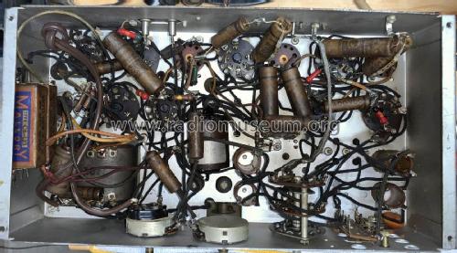
I have owned this console for more than 50 years. Last time it was powered ON must have been 35 years ago. My grand kids want to hear it work so time to restore it. The chassis has no model number. In the pre-internet era it was impossible to identify this 1936 radio. Now I have done that by comparing tube type and layout.
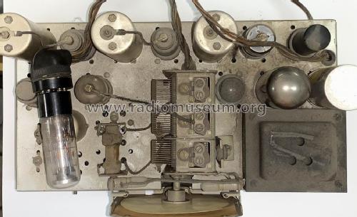
The radio is essentially untouched as shown in the pictures, but many years ago I restored the cabinit to original condition.
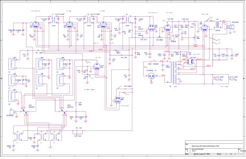
The available schematic from Riders leaves much to the imagination. I have recreated the schematic in OrCad Layout as accurately as I can. Any errors I would appreciate hearing about. This will be challenging becaues I expect all capacitors are bad. If it is appropriate, I will post more pregress pictures.
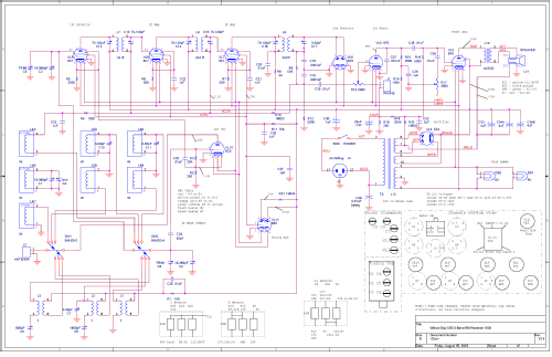
I have updated the schematic to include component locations on the chassis as well as fixing some errors from interpreting the Rider schematic.
I had to remove ALL capacitors and resistors. All resistors were at least 50% high!
Kevin O'Connor, 01.Aug.22
