LH Zenette Ch= 2022
Zenith Radio Corp.; Chicago, IL
- Pays
- Etats-Unis
- Fabricant / Marque
- Zenith Radio Corp.; Chicago, IL
- Année
- 1931/1932
- Catégorie
- Radio - ou tuner d'après la guerre 1939-45
- Radiomuseum.org ID
- 18990
-
- alternative name: Chicago Radio Lab


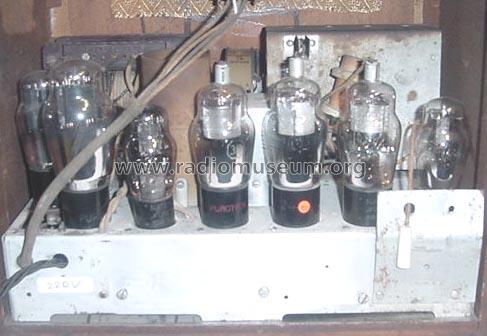
Export Mod. 220 Volt


Cliquez sur la vignette du schéma pour le demander en tant que document gratuit.
- No. de tubes
- 7
- Principe général
- Super hétérodyne avec étage HF; FI/IF 175 kHz
- Circuits accordés
- 7 Circuits MA (AM)
- Gammes d'ondes
- PO uniquement
- Tension / type courant
- Alimentation Courant Alternatif (CA) / 115 Volt
- Haut-parleur
- HP dynamique à électro-aimant (électrodynamique)
- Matière
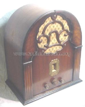
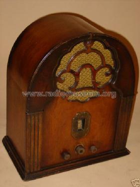
- Boitier en bois
- De Radiomuseum.org
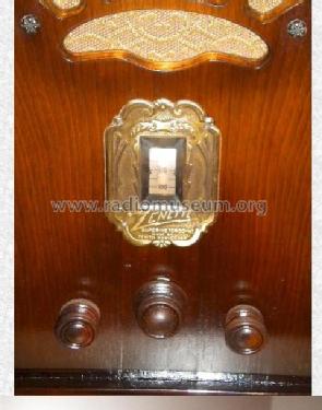
- Modèle: LH Zenette Ch= 2022 - Zenith Radio Corp.; Chicago,
- Forme
- Modèle de table vertical cathédrale (dessus arrondi)
- Remarques
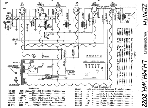
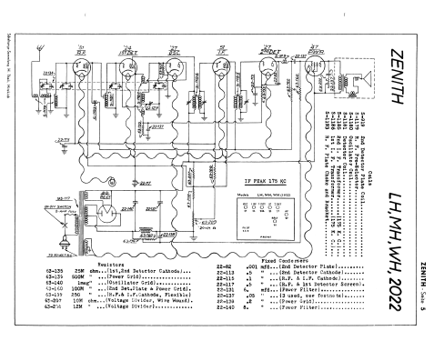
- [3331454B] This model LH Zenette with chassis 2022 has an unusual 4-gang variable condenser but only 3 IF cirquits - in total 7 tuned circuits. There are also export models with other mans transformers.
- Prix de mise sur le marché
- 50.00 $
- Source extérieure
- E. Erb 3-907007-36-0
- Source du schéma
- Rider's Perpetual, Volume 2 = 1932 (Models 1931/1932)
- Littérature
- Radio Collector`s Guide 1921-1932
- Schémathèque (1)
- Thali schematics, Switzerland Zenith page 5
- D'autres Modèles
-
Vous pourrez trouver sous ce lien 4519 modèles d'appareils, 4111 avec des images et 3656 avec des schémas.
Tous les appareils de Zenith Radio Corp.; Chicago, IL
Collections
Le modèle LH Zenette fait partie des collections des membres suivants.
Contributions du forum pour ce modèle: Zenith Radio Corp.;: LH Zenette Ch= 2022
Discussions: 1 | Publications: 1
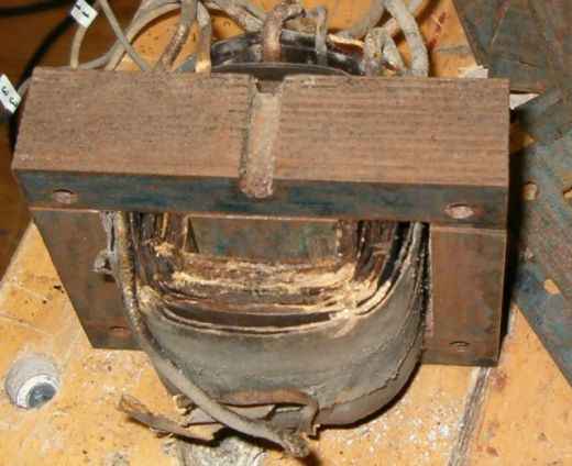
Repair of the Zenette LH transformer.
In my opinion the voltage change from 110 to 220 V, many years ago, seemed the end of life for this radio. To prevent such a mistake a second time I constructed the new transformer ready for the 235 V mains.
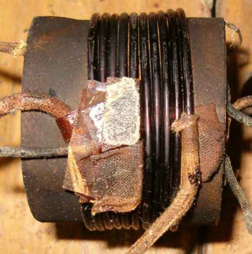
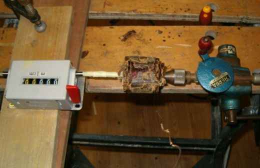
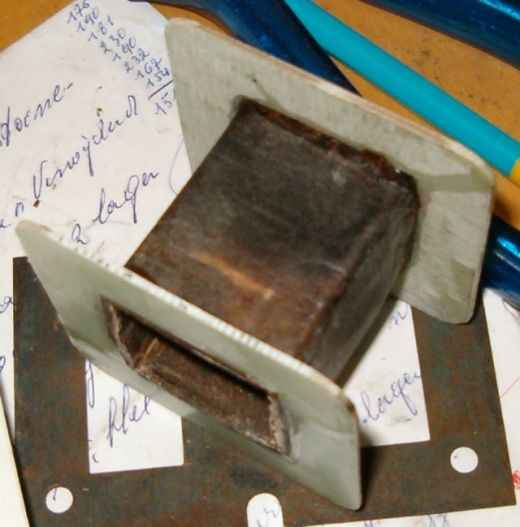
The pictures below nearly tell the whole story. The high voltage secondary was damaged by a short circuit. Counting the windings at disassembly shows 4 turns/volt. For comfort two flanges were added.
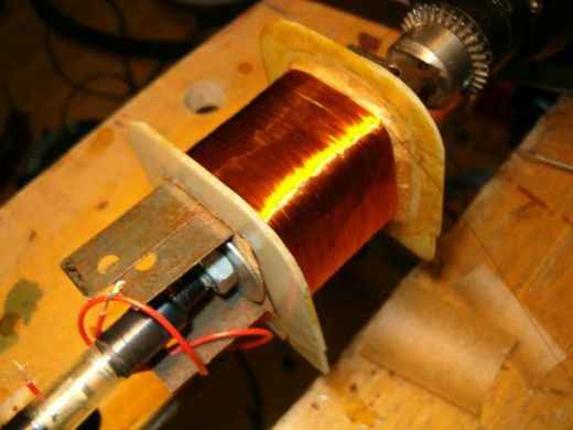
The transformer was rebuilt as follows:
§ High voltage secondary 2760 turns with center tab, dia 0.15 mm (2 x 345 V)
§ Paper
§ Copper screen from the original transformer. Electrical tape is used to prevent the copper foil to act as a short circuit winding.
§ Paper
§ Primary 940 turns, dia 0.35 mm (235 V)
§ Paper
§ 5 volt secondary, 20 turns, dia 1.1 mm
§ Electrical tape for insulation and to fix the wire.
§ 2.5 volt secondary, 10 turns with center tab, 2.5 mm2 multicore wire. The center tab is connected with a 0.5 mm2 wire.
§ Electrical tape
All wire is renewed. Backing paper was used for separation between all layers. The width of the paper is a bit larger than the inner distance between the flanges to ensure good insulation at the outside. Because the original thick 2.5 volt wire was in bad condition I replaced it with 2.5 mm2 multicore wire. This wire has the advantage being very flexible. Winding is done with a 12V-drilling machine. A foot switch applies the 12V power.
Eduard Hontele, 07.May.08