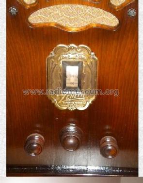
LH Zenette Ch= 2022
Zenith Radio Corp.; Chicago, IL
- País
- Estados Unidos
- Fabricante / Marca
- Zenith Radio Corp.; Chicago, IL
- Año
- 1931/1932
- Categoría
- Radio - o Sintonizador pasado WW2
- Radiomuseum.org ID
- 18990
-
- alternative name: Chicago Radio Lab


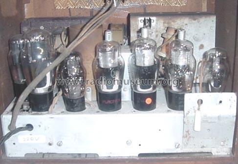
Export Mod. 220 Volt


Haga clic en la miniatura esquemática para solicitarlo como documento gratuito.
- Numero de valvulas
- 7
- Principio principal
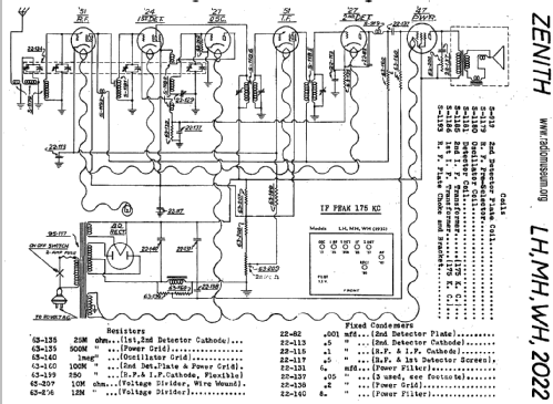
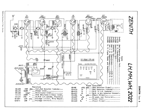
- Superheterodino con paso previo de RF; ZF/IF 175 kHz
- Número de circuitos sintonía
- 7 Circuíto(s) AM
- Gama de ondas
- OM (onda media) solamente
- Tensión de funcionamiento
- Red: Corriente alterna (CA, Inglés = AC) / 115 Volt
- Altavoz
- Altavoz electrodinámico (bobina de campo)
- Material
- Madera
- de Radiomuseum.org
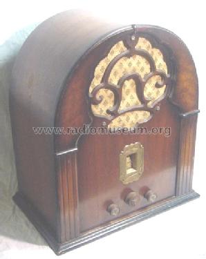
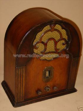
- Modelo: LH Zenette Ch= 2022 - Zenith Radio Corp.; Chicago,
- Forma
- Sobremesa tipo Capilla (upright, round top or pinted arch, not rounded edges only).
- Anotaciones
- [3331454B] This model LH Zenette with chassis 2022 has an unusual 4-gang variable condenser but only 3 IF cirquits - in total 7 tuned circuits. There are also export models with other mans transformers.
- Precio durante el primer año
- 50.00 $
- Ext. procedencia de los datos
- E. Erb 3-907007-36-0
- Procedencia de los datos
- Zenith Radio The Early Years 1919-1935
- Referencia esquema
- Rider's Perpetual, Volume 2 = 1932 (Models 1931/1932)
- Mencionado en
- Radio Collector`s Guide 1921-1932
- Documentación / Esquemas (1)
- Thali schematics, Switzerland Zenith page 5
- Otros modelos
-
Donde encontrará 4519 modelos, 4111 con imágenes y 3656 con esquemas.
Ir al listado general de Zenith Radio Corp.; Chicago, IL
Colecciones
El modelo LH Zenette es parte de las colecciones de los siguientes miembros.
Contribuciones en el Foro acerca de este modelo: Zenith Radio Corp.;: LH Zenette Ch= 2022
Hilos: 1 | Mensajes: 1
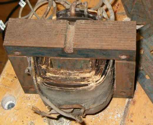
Repair of the Zenette LH transformer.
In my opinion the voltage change from 110 to 220 V, many years ago, seemed the end of life for this radio. To prevent such a mistake a second time I constructed the new transformer ready for the 235 V mains.
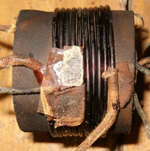
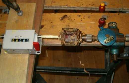
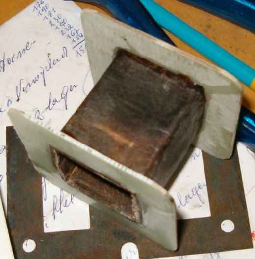
The pictures below nearly tell the whole story. The high voltage secondary was damaged by a short circuit. Counting the windings at disassembly shows 4 turns/volt. For comfort two flanges were added.
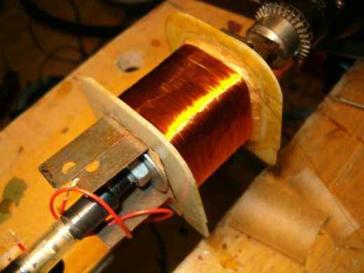
The transformer was rebuilt as follows:
§ High voltage secondary 2760 turns with center tab, dia 0.15 mm (2 x 345 V)
§ Paper
§ Copper screen from the original transformer. Electrical tape is used to prevent the copper foil to act as a short circuit winding.
§ Paper
§ Primary 940 turns, dia 0.35 mm (235 V)
§ Paper
§ 5 volt secondary, 20 turns, dia 1.1 mm
§ Electrical tape for insulation and to fix the wire.
§ 2.5 volt secondary, 10 turns with center tab, 2.5 mm2 multicore wire. The center tab is connected with a 0.5 mm2 wire.
§ Electrical tape
All wire is renewed. Backing paper was used for separation between all layers. The width of the paper is a bit larger than the inner distance between the flanges to ensure good insulation at the outside. Because the original thick 2.5 volt wire was in bad condition I replaced it with 2.5 mm2 multicore wire. This wire has the advantage being very flexible. Winding is done with a 12V-drilling machine. A foot switch applies the 12V power.
Eduard Hontele, 07.May.08