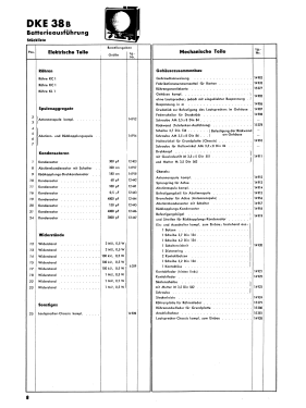
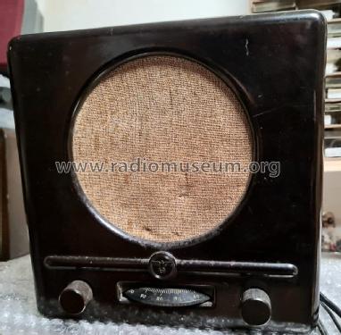
Deutscher Kleinempfänger Batt. DKE-38B DKE-1938B
Eumig, Elektrizitäts und Metallwaren-Industrie-Gesellschaft mbH; Wien
- Pays
- Autriche
- Fabricant / Marque
- Eumig, Elektrizitäts und Metallwaren-Industrie-Gesellschaft mbH; Wien
- Année
- 1939–1945
- Catégorie
- Radio - ou tuner d'après la guerre 1939-45
- Radiomuseum.org ID
- 75358
Cliquez sur la vignette du schéma pour le demander en tant que document gratuit.
- No. de tubes
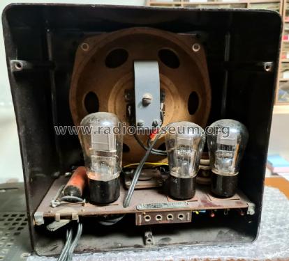
- 3
- Principe général
- Récepteur TRF - par réaction (régénératif)
- Circuits accordés
- 1 Circuits MA (AM)
- Gammes d'ondes
- PO et GO
- Tension / type courant
- Piles (rechargeables ou/et sèches)
- Haut-parleur
- HP magnétique à membrane libre (>1932)
- Matière
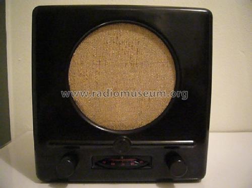
- Boitier en bakélite
- De Radiomuseum.org
- Modèle: Deutscher Kleinempfänger Batt. DKE-38B DKE-1938B - Eumig, Elektrizitäts und
- Forme
- Modèle de table sans poussoirs, modèle cheminée
- Dimensions (LHP)
- 240 x 240 x 120 mm / 9.4 x 9.4 x 4.7 inch
- Remarques
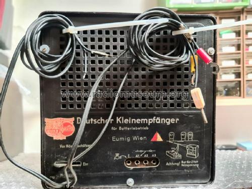
- Es gibt nur einen Batterie-DKE, aber zweierlei Rückwände: "DKE für Batteriebetrieb" sowohl mit als auch ohne die Jahreszahl 1938.
Siehe auch Deutschland. Normalerweise nur unter Gemeinschaftserzeugnisse geführt.
- Source
- Radiokatalog Band 2, Ernst Erb
- Auteur
- Modèle crée par Konrad Birkner † 12.08.2014. Voir les propositions de modification pour les contributeurs supplémentaires.
- D'autres Modèles
-
Vous pourrez trouver sous ce lien 259 modèles d'appareils, 229 avec des images et 177 avec des schémas.
Tous les appareils de Eumig, Elektrizitäts und Metallwaren-Industrie-Gesellschaft mbH; Wien
Collections
Le modèle Deutscher Kleinempfänger Batt. fait partie des collections des membres suivants.
Contributions du forum pour ce modèle: Eumig, Elektrizitäts: Deutscher Kleinempfänger Batt. DKE-38B DKE-1938B
Discussions: 1 | Publications: 7
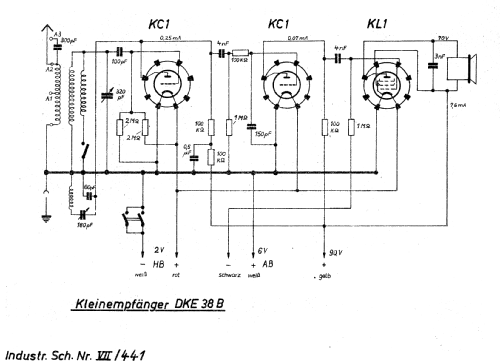
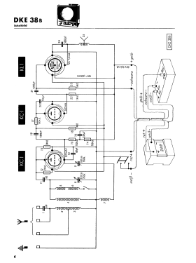
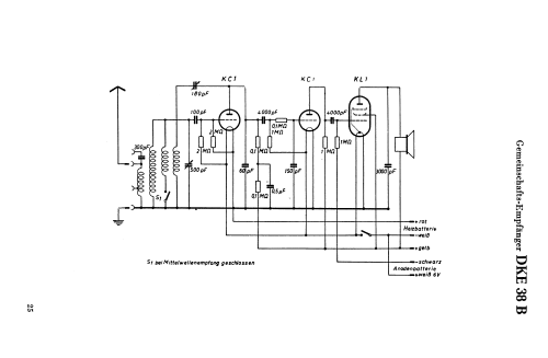
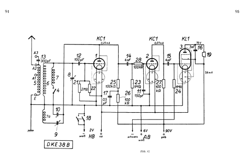
I have started working on my DKE38-B. This radio takes three input voltages, +90, +6, and +2. You'd think this should be pretty straightforward. However, looking at the schematic, I am confused. Look at the +6 volt lead (the "+ weiss" line) in the diagram below:
.jpg)
This appears to be connected directly to ground! Surely this cannot be. On the actual radio, this white wire has a little tag that says "+6 v". If I connect my power supply according to this diagram, I will short it out. Can anyone explain this apparent paradox? I want to be sure I don't make a critical error with this radio. Thanks!
Michele Denber, 16.Nov.10


