Majestic 4019 U Stereo
Grundig (Radio-Vertrieb, RVF, Radiowerke); Fürth/Bayern
- Hersteller / Marke
- Grundig (Radio-Vertrieb, RVF, Radiowerke); Fürth/Bayern
- Jahr
- 1959/1960
- Kategorie
- Rundfunkempfänger (Radio - oder Tuner nach WW2)
- Radiomuseum.org ID
- 90975
-
- anderer Name: Grundig Portugal || Grundig USA / Lextronix


Sams PhotoFact Folder 8, Set 550, DAte 10-61

Picture from Grundig Majestic Brochure

Picture from Grundig Majestic Brochure
Klicken Sie auf den Schaltplanausschnitt, um diesen kostenlos als Dokument anzufordern.
- Anzahl Röhren
- 8
- Anzahl Transistoren
- Halbleiter
- B250C75
- Hauptprinzip
- Superhet allgemein; ZF/IF 460/10700 kHz
- Anzahl Kreise
- 6 Kreis(e) AM 10 Kreis(e) FM
- Wellenbereiche
- Langwelle, Mittelwelle, Kurzwelle und UKW.
- Betriebsart / Volt
- Wechselstromspeisung / 110-120; 220 Volt
- Lautsprecher
- 3 Lautsprecher
- Material
- Gerät mit Holzgehäuse
- von Radiomuseum.org
- Modell: Majestic 4019 U Stereo - Grundig Radio-Vertrieb, RVF,
- Form
- Tischgerät, Tasten oder Druckknöpfe.
- Abmessungen (BHT)
- 610 x 350 x 250 mm / 24 x 13.8 x 9.8 inch
- Bemerkung
-
UKW 88 - 108MHz.
This is the export version of Grundig Konzertgerät 4019 Stereo.
- Literatur/Schema (1)
- -- Original-techn. papers.
- Autor
- Modellseite von Ernst Erb angelegt. Siehe bei "Änderungsvorschlag" für weitere Mitarbeit.
- Weitere Modelle
-
Hier finden Sie 6251 Modelle, davon 5496 mit Bildern und 4255 mit Schaltbildern.
Alle gelisteten Radios usw. von Grundig (Radio-Vertrieb, RVF, Radiowerke); Fürth/Bayern
Sammlungen
Das Modell Majestic befindet sich in den Sammlungen folgender Mitglieder.
Forumsbeiträge zum Modell: Grundig Radio-: Majestic 4019 U Stereo
Threads: 3 | Posts: 11
I have a 4019U that plays very well, but the stereo balance control does not work. After checking all the switch contacts, tubes, capacitors, most of the resistors .Not being familiar with this model, I need some help getting this radio to work properlly.Would someone please help me? Thank you Ross W. Hoff
Ross Hoff, 08.Feb.19
- C58 and C59 values swapped on the Sam's.
- T4 secondary wire colors swapped. Green is ground and puts speaker SP3 electrically out of phase with SP1. The input to V8 is 180 degrees out of phase with V7.
- Page 7, A4 and A14 swapped.
- Page 7, V1 is not ECC83 (12ax7) but is an ECC85 (6AQ8).
- Page 6 step 6, there is no A15 FM IF adjustment.
- Page 6 step 7, A17 will not to to Zero. Refer to 4019 domestic unit procedure www Radiomuseum.org to confirm that A17 is to be adjusted to Minimum voltage.
- Various capacitors are miss labeled and not identified on page 2.
Happy Restorations,
Paul.
Paul E. Pinyot † 2013, 08.Mar.11
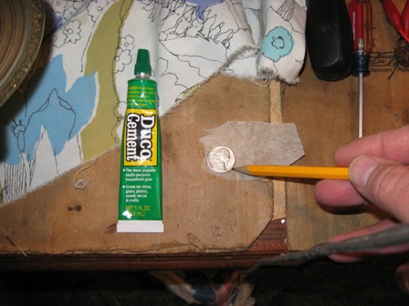
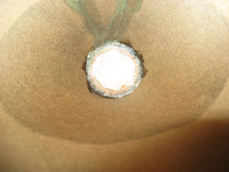
When I first played this radio after the chassis restoration, there was a horrible bass rattle in the oval speaker. When I pulled it for inspection I found all the foam gasket had deteriorated along with the voice coil dust cover.


Paul E. Pinyot † 2013, 03.Mar.11