Majestic 4019 U Stereo
Grundig (Radio-Vertrieb, RVF, Radiowerke); Fürth/Bayern
- Pays
- Allemagne
- Fabricant / Marque
- Grundig (Radio-Vertrieb, RVF, Radiowerke); Fürth/Bayern
- Année
- 1959/1960
- Catégorie
- Radio - ou tuner d'après la guerre 1939-45
- Radiomuseum.org ID
- 90975
-
- alternative name: Grundig Portugal || Grundig USA / Lextronix


Sams PhotoFact Folder 8, Set 550, DAte 10-61

Picture from Grundig Majestic Brochure

Picture from Grundig Majestic Brochure
Cliquez sur la vignette du schéma pour le demander en tant que document gratuit.
- No. de tubes
- 8
- No. de transistors
- Semi-conducteurs
- B250C75
- Principe général
- Super hétérodyne (en général); FI/IF 460/10700 kHz
- Circuits accordés
- 6 Circuits MA (AM) 10 Circuits MF (FM)
- Gammes d'ondes
- PO, GO, OC et FM
- Tension / type courant
- Alimentation Courant Alternatif (CA) / 110-120; 220 Volt
- Haut-parleur
- 3 HP
- Matière
- Boitier en bois
- De Radiomuseum.org
- Modèle: Majestic 4019 U Stereo - Grundig Radio-Vertrieb, RVF,
- Forme
- Modèle de table avec boutons poussoirs.
- Dimensions (LHP)
- 610 x 350 x 250 mm / 24 x 13.8 x 9.8 inch
- Remarques
-
UKW 88 - 108MHz.
This is the export version of Grundig Konzertgerät 4019 Stereo.
- Schémathèque (1)
- -- Original-techn. papers.
- Auteur
- Modèle crée par Ernst Erb. Voir les propositions de modification pour les contributeurs supplémentaires.
- D'autres Modèles
-
Vous pourrez trouver sous ce lien 6245 modèles d'appareils, 5488 avec des images et 4243 avec des schémas.
Tous les appareils de Grundig (Radio-Vertrieb, RVF, Radiowerke); Fürth/Bayern
Collections
Le modèle Majestic fait partie des collections des membres suivants.
Contributions du forum pour ce modèle: Grundig Radio-: Majestic 4019 U Stereo
Discussions: 3 | Publications: 11
I have a 4019U that plays very well, but the stereo balance control does not work. After checking all the switch contacts, tubes, capacitors, most of the resistors .Not being familiar with this model, I need some help getting this radio to work properlly.Would someone please help me? Thank you Ross W. Hoff
Ross Hoff, 08.Feb.19
- C58 and C59 values swapped on the Sam's.
- T4 secondary wire colors swapped. Green is ground and puts speaker SP3 electrically out of phase with SP1. The input to V8 is 180 degrees out of phase with V7.
- Page 7, A4 and A14 swapped.
- Page 7, V1 is not ECC83 (12ax7) but is an ECC85 (6AQ8).
- Page 6 step 6, there is no A15 FM IF adjustment.
- Page 6 step 7, A17 will not to to Zero. Refer to 4019 domestic unit procedure www Radiomuseum.org to confirm that A17 is to be adjusted to Minimum voltage.
- Various capacitors are miss labeled and not identified on page 2.
Happy Restorations,
Paul.
Paul E. Pinyot † 2013, 08.Mar.11
When I first played this radio after the chassis restoration, there was a horrible bass rattle in the oval speaker. When I pulled it for inspection I found all the foam gasket had deteriorated along with the voice coil dust cover.

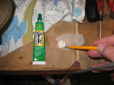

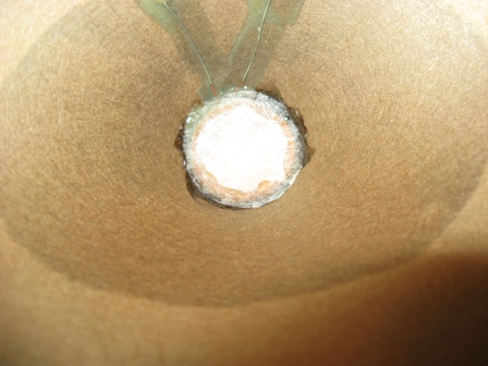


Paul E. Pinyot † 2013, 03.Mar.11