Majestic 4019 U Stereo
Grundig (Radio-Vertrieb, RVF, Radiowerke); Fürth/Bayern
- País
- Alemania
- Fabricante / Marca
- Grundig (Radio-Vertrieb, RVF, Radiowerke); Fürth/Bayern
- Año
- 1959/1960
- Categoría
- Radio - o Sintonizador pasado WW2
- Radiomuseum.org ID
- 90975
-
- alternative name: Grundig Portugal || Grundig USA / Lextronix


Sams PhotoFact Folder 8, Set 550, DAte 10-61

Picture from Grundig Majestic Brochure

Picture from Grundig Majestic Brochure
Haga clic en la miniatura esquemática para solicitarlo como documento gratuito.
- Numero de valvulas
- 8
- Numero de transistores
- Semiconductores
- B250C75
- Principio principal
- Superheterodino en general; ZF/IF 460/10700 kHz
- Número de circuitos sintonía
- 6 Circuíto(s) AM 10 Circuíto(s) FM
- Gama de ondas
- OM, OL, OC y FM
- Tensión de funcionamiento
- Red: Corriente alterna (CA, Inglés = AC) / 110-120; 220 Volt
- Altavoz
- 3 Altavoces
- Material
- Madera
- de Radiomuseum.org
- Modelo: Majestic 4019 U Stereo - Grundig Radio-Vertrieb, RVF,
- Forma
- Sobremesa de botonera.
- Ancho, altura, profundidad
- 610 x 350 x 250 mm / 24 x 13.8 x 9.8 inch
- Anotaciones
-
UKW 88 - 108MHz.
This is the export version of Grundig Konzertgerät 4019 Stereo.
- Documentación / Esquemas (1)
- -- Original-techn. papers.
- Autor
- Modelo creado por Ernst Erb. Ver en "Modificar Ficha" los participantes posteriores.
- Otros modelos
-
Donde encontrará 6240 modelos, 5483 con imágenes y 4238 con esquemas.
Ir al listado general de Grundig (Radio-Vertrieb, RVF, Radiowerke); Fürth/Bayern
Colecciones
El modelo Majestic es parte de las colecciones de los siguientes miembros.
Contribuciones en el Foro acerca de este modelo: Grundig Radio-: Majestic 4019 U Stereo
Hilos: 3 | Mensajes: 11
I have a 4019U that plays very well, but the stereo balance control does not work. After checking all the switch contacts, tubes, capacitors, most of the resistors .Not being familiar with this model, I need some help getting this radio to work properlly.Would someone please help me? Thank you Ross W. Hoff
Ross Hoff, 08.Feb.19
- C58 and C59 values swapped on the Sam's.
- T4 secondary wire colors swapped. Green is ground and puts speaker SP3 electrically out of phase with SP1. The input to V8 is 180 degrees out of phase with V7.
- Page 7, A4 and A14 swapped.
- Page 7, V1 is not ECC83 (12ax7) but is an ECC85 (6AQ8).
- Page 6 step 6, there is no A15 FM IF adjustment.
- Page 6 step 7, A17 will not to to Zero. Refer to 4019 domestic unit procedure www Radiomuseum.org to confirm that A17 is to be adjusted to Minimum voltage.
- Various capacitors are miss labeled and not identified on page 2.
Happy Restorations,
Paul.
Paul E. Pinyot † 2013, 08.Mar.11
When I first played this radio after the chassis restoration, there was a horrible bass rattle in the oval speaker. When I pulled it for inspection I found all the foam gasket had deteriorated along with the voice coil dust cover.

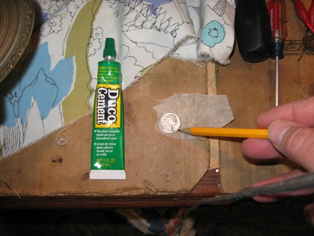

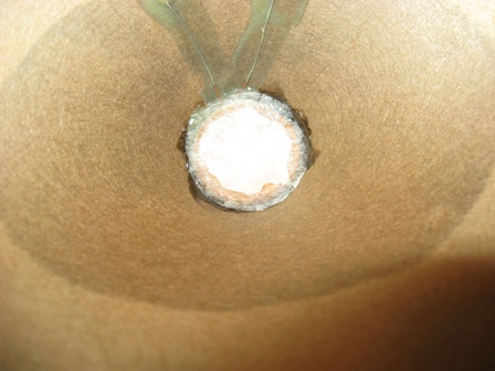


Paul E. Pinyot † 2013, 03.Mar.11