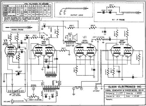
Signal Generator & Tracer KB-141
Olson Radio Corporation, Olson Electronics Inc; Akron, OH
- Pays
- Etats-Unis
- Fabricant / Marque
- Olson Radio Corporation, Olson Electronics Inc; Akron, OH
- Année
- 1959 ??
- Catégorie
- Appareils de mesure et de dépannage (matériel de labo)
- Radiomuseum.org ID
- 248994
Cliquez sur la vignette du schéma pour le demander en tant que document gratuit.
- No. de tubes
- 4
- Gammes d'ondes
- Bandes en notes
- Tension / type courant
- Alimentation Courant Alternatif (CA) / 60 cycles, 120 Volt
- Haut-parleur
- HP dynamique à aimant permanent + bobine mobile
- Matière
- Boitier métallique
- De Radiomuseum.org
- Modèle: Signal Generator & Tracer KB-141 - Olson Radio Corporation, Olson
- Forme
- Modèle de table générique
- Remarques
-
The Olson KB-141 is an AC operated, 4 tube combination signal generator and signal tracer. The signal generator can output either a modulated or unmodulated signal.
The RF Bands have the following frequency ranges:
Band A.............250 - 850kHz
Band B............850 - 3000kHz
Band C............3.0 - 11.0MHz
Band D............11 - 45MHz
Band E............35 - 120MHz
- Auteur
- Modèle crée par Tim Warneka. Voir les propositions de modification pour les contributeurs supplémentaires.
- D'autres Modèles
-
Vous pourrez trouver sous ce lien 42 modèles d'appareils, 38 avec des images et 5 avec des schémas.
Tous les appareils de Olson Radio Corporation, Olson Electronics Inc; Akron, OH
Contributions du forum pour ce modèle: Olson Radio: Signal Generator & Tracer KB-141
Discussions: 1 | Publications: 1
If working on the 4 tube version of this signal generator / tracer, please note that terminals 6 and 7 in the schematic diagram are shown crossed over for the 5687 pre-amplifier tube. Pin 6 should the cathode and 7 is the grid. The tube pin voltage chart also incorrect. The same circuits are used for the Accurate Instruments Model 153 and the schematic diagram for that is correct.
Christopher Cusick, 04.Sep.18

