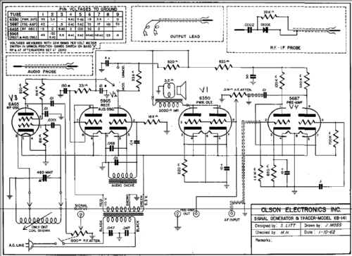
Signal Generator & Tracer KB-141
Olson Radio Corporation, Olson Electronics Inc; Akron, OH
- País
- Estados Unidos
- Fabricante / Marca
- Olson Radio Corporation, Olson Electronics Inc; Akron, OH
- Año
- 1959 ??
- Categoría
- Aparato de medida y servicio (Equipo de laboratorio).
- Radiomuseum.org ID
- 248994
Haga clic en la miniatura esquemática para solicitarlo como documento gratuito.
- Numero de valvulas
- 4
- Gama de ondas
- Bandas de recepción puestas en notas.
- Tensión de funcionamiento
- Red: Corriente alterna (CA, Inglés = AC) / 60 cycles, 120 Volt
- Altavoz
- Altavoz dinámico (de imán permanente)
- Material
- Metálico
- de Radiomuseum.org
- Modelo: Signal Generator & Tracer KB-141 - Olson Radio Corporation, Olson
- Forma
- Sobremesa de cualquier forma, detalles no conocidos.
- Anotaciones
-
The Olson KB-141 is an AC operated, 4 tube combination signal generator and signal tracer. The signal generator can output either a modulated or unmodulated signal.
The RF Bands have the following frequency ranges:
Band A.............250 - 850kHz
Band B............850 - 3000kHz
Band C............3.0 - 11.0MHz
Band D............11 - 45MHz
Band E............35 - 120MHz
- Autor
- Modelo creado por Tim Warneka. Ver en "Modificar Ficha" los participantes posteriores.
- Otros modelos
-
Donde encontrará 42 modelos, 38 con imágenes y 5 con esquemas.
Ir al listado general de Olson Radio Corporation, Olson Electronics Inc; Akron, OH
Contribuciones en el Foro acerca de este modelo: Olson Radio: Signal Generator & Tracer KB-141
Hilos: 1 | Mensajes: 1
If working on the 4 tube version of this signal generator / tracer, please note that terminals 6 and 7 in the schematic diagram are shown crossed over for the 5687 pre-amplifier tube. Pin 6 should the cathode and 7 is the grid. The tube pin voltage chart also incorrect. The same circuits are used for the Accurate Instruments Model 153 and the schematic diagram for that is correct.
Christopher Cusick, 04.Sep.18

