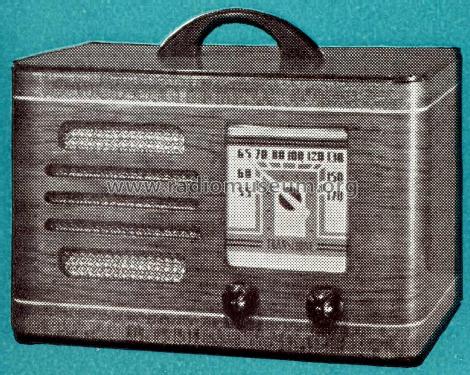
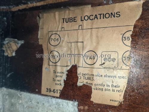
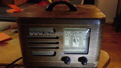
TH-14 Transitone
Philco, Philadelphia Stg. Batt. Co.; USA
- País
- Estados Unidos
- Fabricante / Marca
- Philco, Philadelphia Stg. Batt. Co.; USA
- Año
- 1939/1940
- Categoría
- Radio - o Sintonizador pasado WW2
- Radiomuseum.org ID
- 51579
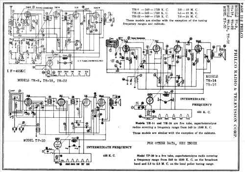
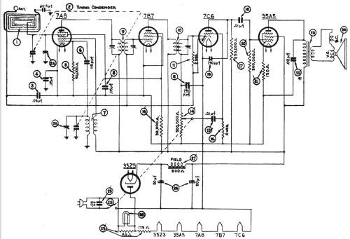
Haga clic en la miniatura esquemática para solicitarlo como documento gratuito.
- Numero de valvulas
- 5
- Principio principal
- Superheterodino en general; ZF/IF 455 kHz; 2 Etapas de AF
- Gama de ondas
- OM (onda media) solamente
- Tensión de funcionamiento
- Red: Aparato AC/DC. / 115 Volt
- Altavoz
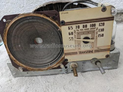
- Altavoz electrodinámico (bobina de campo)
- Material
- Madera
- de Radiomuseum.org
- Modelo: TH-14 Transitone - Philco, Philadelphia Stg. Batt
- Forma
- Sobremesa de tamaño mediano sin botonera <= 35 cm. (Incluso portables pero sólo con alimantación por red).
- Anotaciones
-
The Philco models TH-14 and model TH-16 are similar, except for the cabinets. Number made: 9,020
- Precio durante el primer año
- 18.00 $
- Ext. procedencia de los datos
- Ernst Erb
- Procedencia de los datos
- The Radio Collector's Directory and Price Guide 1921 - 1965
- Referencia esquema
- Rider's Perpetual, Volume 12 = ca. 1941 and before
- Mencionado en
- Philco Radio 1928-1942
- Documentación / Esquemas (1)
- Philco 1940 RMS Yearbook
- Documentación / Esquemas (2)
- Machine Age to Jet Age II (page 224.)
- Documentación / Esquemas (3)
- Philco Folder PR-738, 1938-1940.
- Otros modelos
-
Donde encontrará 4086 modelos, 2222 con imágenes y 3734 con esquemas.
Ir al listado general de Philco, Philadelphia Stg. Batt. Co.; USA
Colecciones
El modelo TH-14 es parte de las colecciones de los siguientes miembros.
Contribuciones en el Foro acerca de este modelo: Philco, Philadelphia: TH-14 Transitone
Hilos: 1 | Mensajes: 5
Hello, dear Radio Collectors! Here's a new mystery - I'm working on a Philco TH-14 Transitone. I replaced all the capacitors and all the rotten rubber insulated wiring. I applied power and got nothing, not even a hum in the speaker at any volume level. Here's the details so far:
B+ = 146 v.
Audio output tube (35A5):
grid, pin 6, normal audio waveform that varies with the tuning capacitor
plate, pin 2, 146 v. DC, zero AC (shouldn't I see an AC waveform here?)
130 ohm R21 measures 144 ohms.
Audio output transformer primary: 183.8 ohms
Across speaker terminals: 1.8 ohms
C22 (which I just replaced anyway) is OK
I tried a different output tube with the same results.
Does anyone have an idea what might be wrong or how to proceed from here?
Also, can someone tell me what the notations on the schematic by the speaker mean? They look like "V.E." and "D.C.", but I have no idea what they mean there.
Thanks / danke sehr!
Michele Denber, 19.Apr.09
