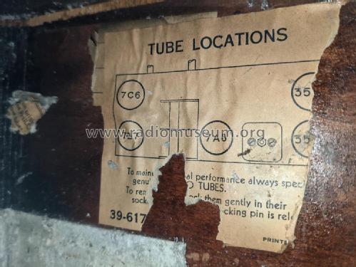
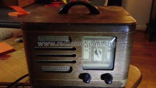
TH-14 Transitone
Philco, Philadelphia Stg. Batt. Co.; USA
- Land
- USA
- Hersteller / Marke
- Philco, Philadelphia Stg. Batt. Co.; USA
- Jahr
- 1939/1940
- Kategorie
- Rundfunkempfänger (Radio - oder Tuner nach WW2)
- Radiomuseum.org ID
- 51579
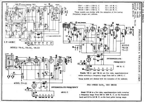
Klicken Sie auf den Schaltplanausschnitt, um diesen kostenlos als Dokument anzufordern.
- Anzahl Röhren
- 5
- Hauptprinzip
- Superhet allgemein; ZF/IF 455 kHz; 2 NF-Stufe(n)
- Wellenbereiche
- Mittelwelle, keine anderen.
- Betriebsart / Volt
- Allstromgerät / 115 Volt
- Lautsprecher
- Dynamischer LS, mit Erregerspule (elektrodynamisch)
- Material
- Gerät mit Holzgehäuse
- von Radiomuseum.org
- Modell: TH-14 Transitone - Philco, Philadelphia Stg. Batt
- Form
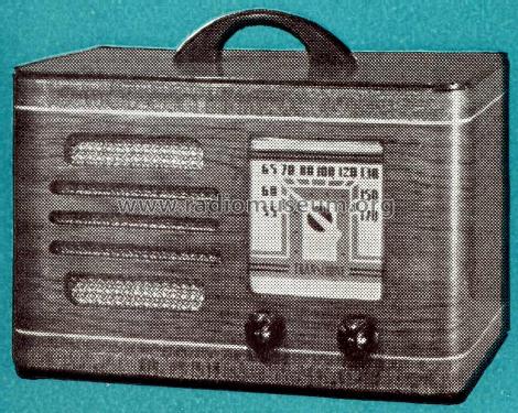
- Tischgerät ohne Drucktasten, bis 35 cm Breite (Kleingerät, meist dekorativ. Nur für Netzbetrieb, doch Transportgriff möglich).
- Bemerkung
-
The Philco models TH-14 and model TH-16 are similar, except for the cabinets. Number made: 9,020
- Originalpreis
- 18.00 $
- Datenherkunft extern
- Ernst Erb
- Schaltungsnachweis
- Rider's Perpetual, Volume 12 = ca. 1941 and before
- Literaturnachweis
- Philco Radio 1928-1942
- Literatur/Schema (1)
- Philco 1940 RMS Yearbook
- Literatur/Schema (2)
- Machine Age to Jet Age II (page 224.)
- Literatur/Schema (3)
- Philco Folder PR-738, 1938-1940.
- Weitere Modelle
-
Hier finden Sie 4120 Modelle, davon 2227 mit Bildern und 3768 mit Schaltbildern.
Alle gelisteten Radios usw. von Philco, Philadelphia Stg. Batt. Co.; USA
Sammlungen
Das Modell TH-14 befindet sich in den Sammlungen folgender Mitglieder.
Forumsbeiträge zum Modell: Philco, Philadelphia: TH-14 Transitone
Threads: 1 | Posts: 5
Hello, dear Radio Collectors! Here's a new mystery - I'm working on a Philco TH-14 Transitone. I replaced all the capacitors and all the rotten rubber insulated wiring. I applied power and got nothing, not even a hum in the speaker at any volume level. Here's the details so far:
B+ = 146 v.
Audio output tube (35A5):
grid, pin 6, normal audio waveform that varies with the tuning capacitor
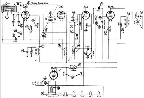
plate, pin 2, 146 v. DC, zero AC (shouldn't I see an AC waveform here?)
130 ohm R21 measures 144 ohms.
Audio output transformer primary: 183.8 ohms
Across speaker terminals: 1.8 ohms
C22 (which I just replaced anyway) is OK
I tried a different output tube with the same results.
Does anyone have an idea what might be wrong or how to proceed from here?
Also, can someone tell me what the notations on the schematic by the speaker mean? They look like "V.E." and "D.C.", but I have no idea what they mean there.
Thanks / danke sehr!
Michele Denber, 19.Apr.09
