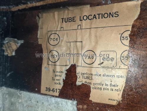
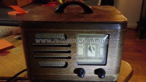
TH-14 Transitone
Philco, Philadelphia Stg. Batt. Co.; USA
- Produttore / Marca
- Philco, Philadelphia Stg. Batt. Co.; USA
- Anno
- 1939/1940
- Categoria
- Radio (o sintonizzatore del dopoguerra WW2)
- Radiomuseum.org ID
- 51579
Clicca sulla miniatura dello schema per richiederlo come documento gratuito.
- Numero di tubi
- 5
- Principio generale
- Supereterodina (in generale); ZF/IF 455 kHz; 2 Stadi BF
- Gamme d'onda
- Solo onde medie (OM).
- Tensioni di funzionamento
- Alimentazione universale (doppia: CC/CA) / 115 Volt
- Altoparlante
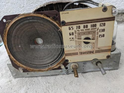
- AP elettrodinamico (bobina mobile e bobina di eccitazione/di campo)
- Materiali
- Mobile in legno
- Radiomuseum.org
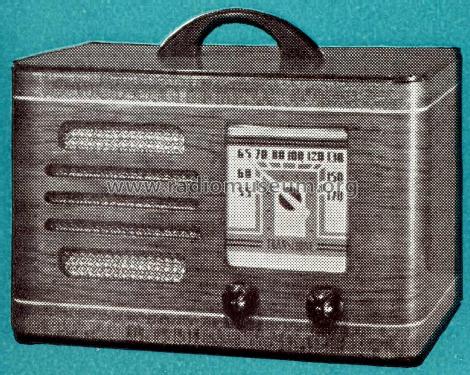
- Modello: TH-14 Transitone - Philco, Philadelphia Stg. Batt
- Forma
- Soprammobile compatto/con bordi arrotondati/midget senza pulsantiera/tastiera.<= 35 cm (Sometimes with handle but for mains only).
- Annotazioni
-
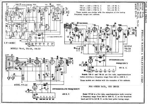
The Philco models TH-14 and model TH-16 are similar, except for the cabinets. Number made: 9,020
- Prezzo nel primo anno
- 18.00 $
- Fonte esterna dei dati
- Ernst Erb
- Fonte dei dati
- The Radio Collector's Directory and Price Guide 1921 - 1965
- Riferimenti schemi
- Rider's Perpetual, Volume 12 = ca. 1941 and before
- Bibliografia
- Philco Radio 1928-1942
- Letteratura / Schemi (1)
- Philco 1940 RMS Yearbook
- Letteratura / Schemi (2)
- Machine Age to Jet Age II (page 224.)
- Letteratura / Schemi (3)
- Philco Folder PR-738, 1938-1940.
- Altri modelli
-
In questo link sono elencati 4120 modelli, di cui 2227 con immagini e 3768 con schemi.
Elenco delle radio e altri apparecchi della Philco, Philadelphia Stg. Batt. Co.; USA
Collezioni
Il modello TH-14 fa parte delle collezioni dei seguenti membri.
Discussioni nel forum su questo modello: Philco, Philadelphia: TH-14 Transitone
Argomenti: 1 | Articoli: 5
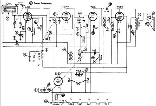
Hello, dear Radio Collectors! Here's a new mystery - I'm working on a Philco TH-14 Transitone. I replaced all the capacitors and all the rotten rubber insulated wiring. I applied power and got nothing, not even a hum in the speaker at any volume level. Here's the details so far:
B+ = 146 v.
Audio output tube (35A5):
grid, pin 6, normal audio waveform that varies with the tuning capacitor
plate, pin 2, 146 v. DC, zero AC (shouldn't I see an AC waveform here?)
130 ohm R21 measures 144 ohms.
Audio output transformer primary: 183.8 ohms
Across speaker terminals: 1.8 ohms
C22 (which I just replaced anyway) is OK
I tried a different output tube with the same results.
Does anyone have an idea what might be wrong or how to proceed from here?
Also, can someone tell me what the notations on the schematic by the speaker mean? They look like "V.E." and "D.C.", but I have no idea what they mean there.
Thanks / danke sehr!
Michele Denber, 19.Apr.09
