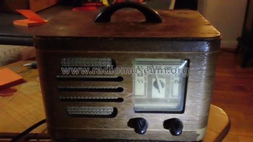
TH-14 Transitone
Philco, Philadelphia Stg. Batt. Co.; USA
- Pays
- Etats-Unis
- Fabricant / Marque
- Philco, Philadelphia Stg. Batt. Co.; USA
- Année
- 1939/1940
- Catégorie
- Radio - ou tuner d'après la guerre 1939-45
- Radiomuseum.org ID
- 51579
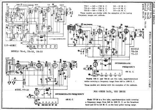
Cliquez sur la vignette du schéma pour le demander en tant que document gratuit.
- No. de tubes
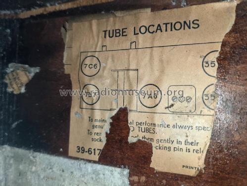
- 5
- Principe général
- Super hétérodyne (en général); FI/IF 455 kHz; 2 Etage(s) BF
- Gammes d'ondes
- PO uniquement
- Tension / type courant
- Appareil tous courants (CA / CC) / 115 Volt
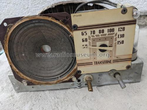
- Haut-parleur
- HP dynamique à électro-aimant (électrodynamique)
- Matière
- Boitier en bois
- De Radiomuseum.org
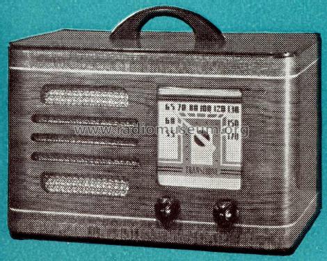
- Modèle: TH-14 Transitone - Philco, Philadelphia Stg. Batt
- Forme
- Modèle de table sans poussoirs, modèle cheminée
- Remarques
-
The Philco models TH-14 and model TH-16 are similar, except for the cabinets. Number made: 9,020
- Prix de mise sur le marché
- 18.00 $
- Source extérieure
- Ernst Erb
- Source du schéma
- Rider's Perpetual, Volume 12 = ca. 1941 and before
- Littérature
- Philco Radio 1928-1942
- Schémathèque (1)
- Philco 1940 RMS Yearbook
- Schémathèque (2)
- Machine Age to Jet Age II (page 224.)
- Schémathèque (3)
- Philco Folder PR-738, 1938-1940.
- D'autres Modèles
-
Vous pourrez trouver sous ce lien 4120 modèles d'appareils, 2227 avec des images et 3768 avec des schémas.
Tous les appareils de Philco, Philadelphia Stg. Batt. Co.; USA
Collections
Le modèle TH-14 fait partie des collections des membres suivants.
Contributions du forum pour ce modèle: Philco, Philadelphia: TH-14 Transitone
Discussions: 1 | Publications: 5
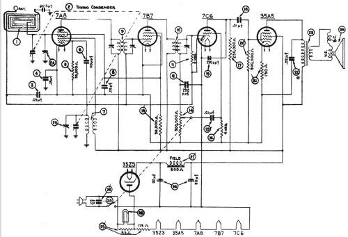
Hello, dear Radio Collectors! Here's a new mystery - I'm working on a Philco TH-14 Transitone. I replaced all the capacitors and all the rotten rubber insulated wiring. I applied power and got nothing, not even a hum in the speaker at any volume level. Here's the details so far:
B+ = 146 v.
Audio output tube (35A5):
grid, pin 6, normal audio waveform that varies with the tuning capacitor
plate, pin 2, 146 v. DC, zero AC (shouldn't I see an AC waveform here?)
130 ohm R21 measures 144 ohms.
Audio output transformer primary: 183.8 ohms
Across speaker terminals: 1.8 ohms
C22 (which I just replaced anyway) is OK
I tried a different output tube with the same results.
Does anyone have an idea what might be wrong or how to proceed from here?
Also, can someone tell me what the notations on the schematic by the speaker mean? They look like "V.E." and "D.C.", but I have no idea what they mean there.
Thanks / danke sehr!
Michele Denber, 19.Apr.09
