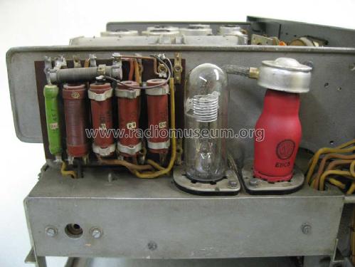
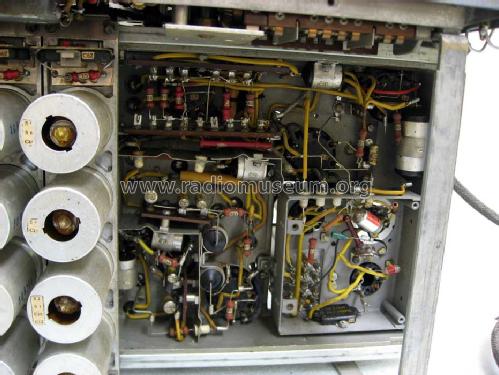
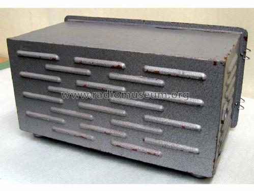
HMZL/34 OKM
Philips Radios - Deutschland
- Paese
- Germania
- Produttore / Marca
- Philips Radios - Deutschland
- Anno
- 1942 ?
- Categoria
- Ricevitore professionale (può includere bande amatoriali)
- Radiomuseum.org ID
- 126300
-
- Brand: Deutsche Philips-Ges.
Clicca sulla miniatura dello schema per richiederlo come documento gratuito.
- Numero di tubi
- 9
- Principio generale
- Supereterodina con stadio RF; ZF/IF 280 kHz
- N. di circuiti accordati
- 8 Circuiti Mod. Amp. (AM)
- Gamme d'onda
- Onde medie (OM) e più di 2 gamme di onde corte (> 2 x OC).
- Tensioni di funzionamento
- Alimentazione a corrente alternata (CA) / 110; 125; 145; 200; 220; 245 Volt
- Altoparlante
- - Per cuffie o amplificatori esterni
- Materiali
- Mobile di metallo
- Radiomuseum.org
- Modello: HMZL/34 OKM - Philips Radios - Deutschland
- Forma
- Boatanchor (pesante apparecchio militare o commerciale, > 20 kg)
- Dimensioni (LxAxP)
- 517 x 275 x 275 mm / 20.4 x 10.8 x 10.8 inch
- Annotazioni
-
Bereich 1 = 1,50 ... 2,40 MHz
Bereich 2 = 2,40 ... 4,00 MHz
Bereich 3 = 4,00 ... 6,45 MHz
Bereich 4 = 6,45 ... 10,6 MHz
Bereich 5 = 10,6 ... 16,5 MHz
Bereich 6 = 16,5 ... 23,1 MHz
Gewicht gemessen ohne Netzanschlußgerät.Als Netzgerät wurde bei der deutschen Marine z.B. der Typ U.O.R.1 vewendet.
- Peso netto
- 22 kg / 48 lb 7.3 oz (48.458 lb)
- Letteratura / Schemi (1)
- -- Original-techn. papers.
- Autore
- Modello inviato da Geert Schulte. Utilizzare "Proponi modifica" per inviare ulteriori dati.
- Altri modelli
-
In questo link sono elencati 2543 modelli, di cui 2255 con immagini e 1564 con schemi.
Elenco delle radio e altri apparecchi della Philips Radios - Deutschland
Discussioni nel forum su questo modello: Philips Radios -: HMZL/34 OKM
Argomenti: 1 | Articoli: 2
Dear fellow collectors,
in order to bring my HMZL back to working condition, I need documentation for the U.O.R.1 universal power supply. It's an impressive device with a big power transformer, two choppers, and a whole lot of chokes and electrolytics. There is a switchboard that allows the unit to be set for a whole range of input power options, A.C. and D.C.
Unfortunately, my unit was not only repaired, but modified along the way. Some caps were replaced, some of the wiring was changed, and some resistors bypassed. I could probably fix it for A.C. operation, but in order to achieve full service for D.C. as well, I need your help. Has anyone got a schematic, or has maybe seen/worked/repaired a unit in original condition?
Your help is appreciated,
Nikolaus Loewe
Nikolaus Löwe, 09.Dec.13


